Parameter
structure
Keypad and
display
Parameter x.00
Parameter
description format
Advanced parameter
descriptions
Serial comms
protocol
Electronic
nameplate
Performance
Menu 10
Digitax ST Advanced User Guide 127
Issue Number: 1 www.controltechniques.com
C.rtg SMARTCARD trip: The voltage and/or current rating of the source and destination drives are different
186
Drive rating dependent parameters (parameters with the RA coding) are likely to have different values and ranges with drives of
different voltage and current ratings. Parameters with this attribute will not be transferred to the destination drive by SMARTCARDs
when the rating of the destination drive is different from the source drive and the file is a parameter file. Drive rating dependent
parameters will be transferred if only the current rating is different and the file is a differences from default type file.
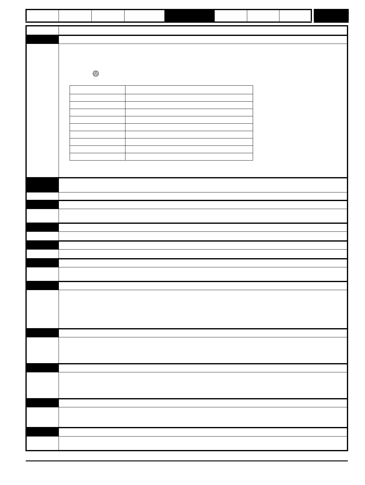
Press the red reset button
Drive rating parameters are:
The above parameters will be set to their default values.
C.SLX
An error has occurred when attempting to transfer a user program from a Solutions Module to a SMARTCARD and vice
versa
172,173,174 See Pr 11.37 for more details
C.TyP SMARTCARD trip: SMARTCARD parameter set not compatible with drive
187
Press the reset button
Ensure destination drive type is the same as the source parameter file drive type
dESt Two or more parameters are writing to the same destination parameter
199 Set Pr xx.00 = 12001 check all visible parameters in the menus for duplication
EEF EEPROM data corrupted - Serial comms will timeout with remote keypad on the drive RS485 comms port.
31 This trip can only be cleared by loading default parameters and saving parameters
EnC1 Drive encoder trip: Encoder power supply overload
189
Check encoder power supply wiring and encoder current requirement
Maximum current = 200mA @ 15V, or 300mA @ 8V and 5V
EnC2 Drive encoder trip: Wire break (Drive encoder terminals 1 & 2, 3 & 4, 5 & 6)
190
Check cable continuity
Check wiring of feedback signals is correct
Check encoder power is set correctly
Check that the encoder cable is connected to the right encoder port on the drive (not to the buffered encoder output port)
Replace feedback device
If wire break detection on the main drive encoder input is not required, set Pr 3.40 = 0 to disable the EnC2 trip
EnC3 Drive encoder trip: Phase offset incorrect While running
191
Check the encoder signal for noise
Check encoder shielding
Check the integrity of the encoder mechanical mounting
Repeat the offset measurement test
EnC4 Drive encoder trip: Feedback device comms failure
192
Ensure encoder power supply is correct
Ensure baud rate is correct
Check encoder wiring
Replace feedback device
EnC5 Drive encoder trip: Checksum or CRC error
193
Check the encoder signal for noise
Check the encoder cable shielding
With EnDat encoders, check the comms resolution and/or carry out the auto-configuration Pr 3.41
EnC6
Drive encoder trip: Encoder has indicated an error
194
Replace feedback device
With SSI encoders, check the wiring and encoder supply setting
Trip Diagnosis
Parameter Function
2.08 Standard ramp voltage
4.05/6/7, 21.27/8/9 Current limits
4.24 User current maximum scaling
5.07, 21.07 Motor rated current
5.09, 21.09 Motor rated voltage
5.17, 21.12 Stator resistance
5.18 Switching frequency
5.24, 21.14 Transient inductance
6.48 Line power supply loss ride through detection level