Menu 10
Parameter
structure
Keypad and
display
Parameter x.00
Parameter
description format
Advanced parameter
descriptions
Serial comms
protocol
Electronic
nameplate
Performance
140 Digitax ST Advanced User Guide
www.controltechniques.com Issue Number: 1
This parameter defines the time between periods when the braking IGBT is on for the full power braking time so that the average power in the resistor
does not exceed the rating of the resistor.
For DST1xxxx, the default value is a suitable value for standard braking resistors that can be mounted within the drive as given in the table below.
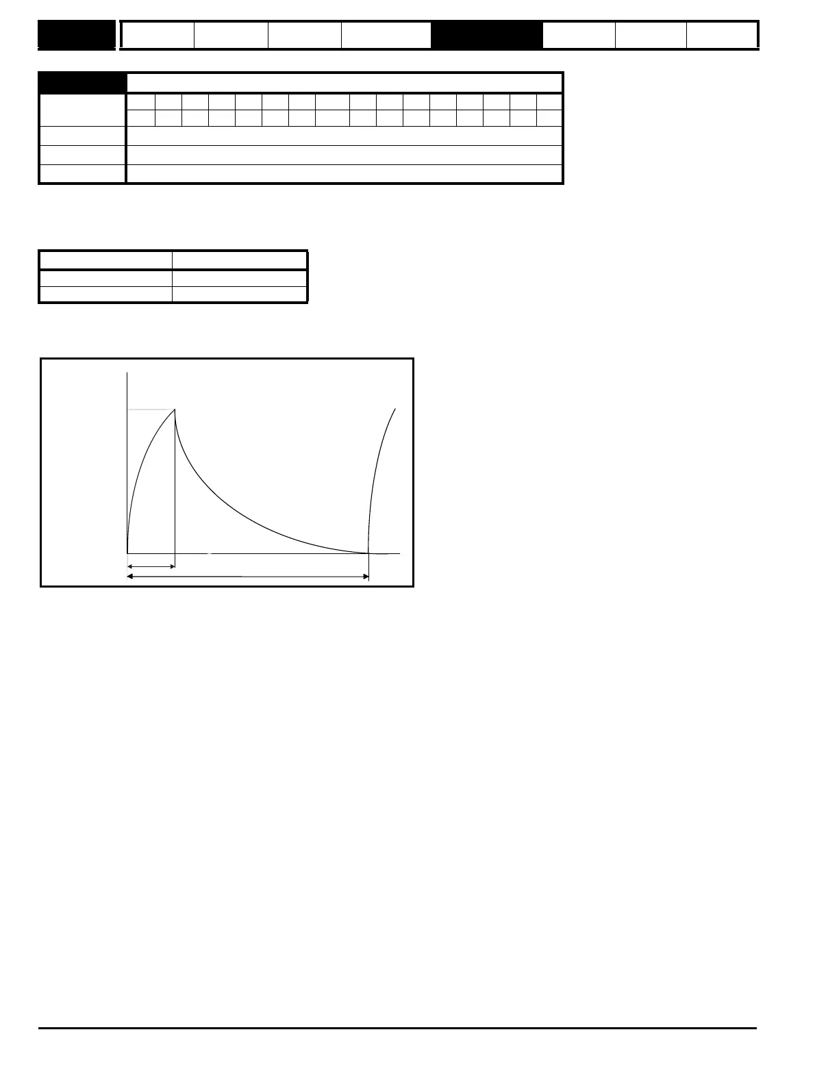
The braking resistor temperature is modelled by the drive as shown below. The temperature rises in proportion to the power flowing into the resistor
and falls in proportion to the difference between the resistor temperature and ambient. Under the conditions shown the resistor is heating up just to
100% of its rated temperature during each braking period.
Assuming that the full power braking time is much shorter than the full power braking period i.e. Pr 10.30 < Pr 10.31 / 10 (which is normally the case)
the values for Pr 10.30 and Pr 10.31 can be calculated as follows:
Power flowing into the resistor when the braking IGBT is on, P
on
= Full braking volts
2
/ R
Where:
Full braking volts is defined in the table and R is the resistance of the braking resistor.
Full power braking time (Pr 10.30), T
on
= E / P
on
Where:
E is the total energy that can be absorbed by the resistor when its initial temperature is ambient temperature.
Therefore full power braking time (Pr 10.30), T
on
= E x R / Full braking volts
2
If the average power rating of the resistor is not to be exceeded in the cycle shown in the diagram above, the average power in the resistor is given
by, P
av
= P
on
x T
on
/ Tp
Where:
Tp is the full power braking period
Also, P
on
= E / T
on
Therefore P
av
= E / Tp
Therefore full power braking period (Pr 10.31), Tp = E / P
av
The resistance of the braking resistor R, the total energy E and the average power P
av
can normally be obtained for the resistor and used to calculate
Pr 10.30 and Pr 10.31.
If the profile of the power flowing from the motor is know then the instantaneous temperature can be calculated at any point by simulating the braking
resistor with the model shown below.
10.31 Full power braking period
Coding
Bit SP FI DE Txt VM DP ND RA NC NV PT US RW BU PS
1 111
Range 0.0 to 1500.0 s
Default Refer to table below
Update rate Background read
Drive voltage rating Parameter default
200V 2.6s
400V 1.7s
0
100
%
t
Pr
10.30
Pr
10.31
Overload
accumulator
Pr
10.39