Menu 10
Parameter
structure
Keypad and
display
Parameter x.00
Parameter
description format
Advanced parameter
descriptions
Serial comms
protocol
Electronic
nameplate
Performance
142 Digitax ST Advanced User Guide
www.controltechniques.com Issue Number: 1
Each bit in this parameter has the following functions:
Stop on non-important trips
If bit 0 is set to zero then the drive simply trips when a non-important trip occurs. Non-important trips are: th, ths, Old1, cL2, cL3, SCL. If bit 0 is set to
one the drive will stop before tripping when one of these trips is initiated.
Disable braking IGBT trips
For details of braking IGBT trip mode see Pr 10.31.
Disable phase loss trip
The user can disable the phase loss trip in 200V drives as these are allowed to operate from a single phase supply. If bit 2 is set to zero the phase
loss trip is enabled. If bit 2 is set to one the phase loss trip is disabled in 200V drives only.
Disable braking resistor temperature monitoring failure detection
Digitax ST has an internal user fit braking resistor with a thermistor to detect overheating of the resistor. As default bit 3 of Pr 10.37 is set to zero, and
so if the braking resistor and its thermistor is not installed the drive will produce a trip (br.th) because the thermistor appears to be open circuit. This
trip can be disabled so that the drive can run by setting bit 3 of Pr 10.37 to one. If the resistor is installed then no trip is produced unless the thermistor
fails, and so bit 3 of Pr 10.37 can be left at zero.
Example: For a single phase drive with no internal brake resistor fitted, this parameter should be set to 12 (Binary 1100).
When a value other than zero is written to the user trip parameter the actions described in the following table are performed. The drive immediately
writes the value back to zero. If the value is not included in the table a trip is initiated with the same trip number as the value provided the drive is not
already tripped.
This parameter gives an indication of braking resistor temperature based on a simple thermal model, see Pr 10.30 and Pr 10.31 on page 140. Zero
indicates the resistor is close to ambient and 100% is the maximum temperature (trip level). A br.rS warning is given if this parameter is above 75%
and the braking IGBT active.
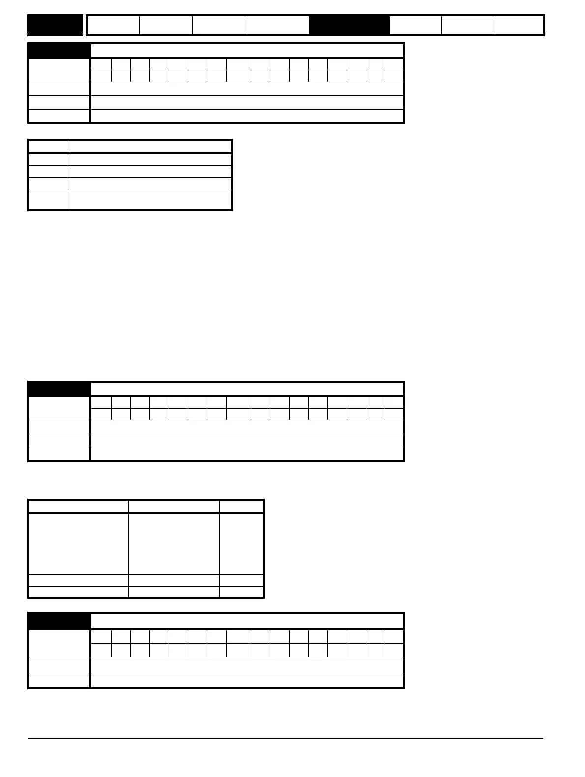
10.37 Action on trip detection
Coding
Bit SP FI DE Txt VM DP ND RA NC NV PT US RW BU PS
111
Range 0 to 15
Default 0
Update rate Background read
Bit Function
0 Stop on non-important trips
1 Disable braking IGBT trips
2 Disable phase loss trip
3
Disable braking resistor temperature
monitoring failure detection
10.38 User trip
Coding
Bit SP FI DE Txt VM DP ND RA NC NV PT US RW BU PS
111
Range 0 to 255
Default 0
Update rate Background read
Action Values written to 10.38 Trip code
No action
1
31
200
205
210
217-245
UV
EEF
SL1.HF
SL2.HF
SL3.HF
HFx
Drive reset 100
Clear trip and trip time logs 255
10.39 Braking energy overload accumulator
Coding
Bit SP FI DE Txt VM DP ND RA NC NV PT US RW BU PS
11 1 1 1
Range 0.0 to 100.0 %
Update rate Background read