Menu 11
Parameter
structure
Keypad and
display
Parameter x.00
Parameter
description format
Advanced parameter
descriptions
Serial comms
protocol
Electronic
nameplate
Performance
146 Digitax ST Advanced User Guide
www.controltechniques.com Issue Number: 1
The following product specific limitations apply:
• Maximum slave response time when accessing the drive is 100ms
• Maximum number of 16 bit registers that can be written to, or read from, the drive itself is limited to 16
• Maximum number of 16 bit registers that can be written to, or read from, a Solutions Module or via a Solutions Module - see Solutions Module
User Guide
• The communications buffer can hold a maximum of 128bytes
Modbus RTU protocol, but with SM-Keypad Plus only
This setting is used for disabling comms access when the SM-Keypad Plus is used as a hardware key. See the SM-Keypad Plus User Guide for more
information.
Used in all comms modes to define the baud rate.
*Modbus RTU only
This parameter can be changed via the drive keypad, via a Solutions Module or via the comms interface itself. If it is changed via the comms
interface, the response to the command uses the original baud rate. The master should wait at least 20ms before sending a new message using the
new baud rate.
There will always be a finite delay between the end of a message from the host (master) and the time at which the host is ready to receive the
response from the drive (slave). The drive does not respond until at least 1ms after the message has been received from the host allowing 1ms for the
host to change from transmit to receive mode. This initial delay can be extended using Pr 11.26 if required for both ANSI and Modbus RTU protocols.
Note that the drive holds its own transmitters active for up to 1ms after it has transmitted data before switching to the receive mode, the host should
not send any data during this time.
Modbus RTU uses a silent period detection system to detect the end of a message. This silent period is either the length of time for 3.5 characters at
the present baud rate or the length of time set in Pr 11.26, whichever is the longest.
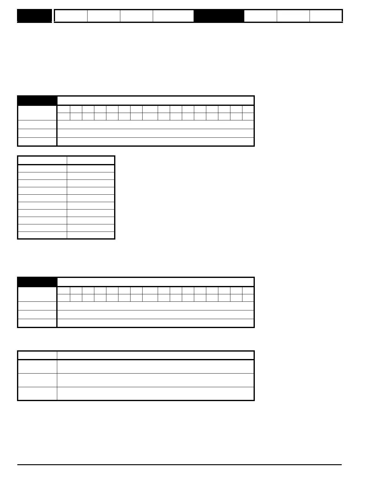
11.25 Baud rate
Coding
Bit SP FI DE Txt VM DP ND RA NC NV PT US RW BU PS
1 111
Range 0 to 9
Default 6
Update rate Background read
Parameter value String/baud rate
0 300
1 600
2 1200
3 2400
4 4800
5 9600
6 19200
7 38400
8* 57600
9* 115200
11.26 Minimum comms transmit delay
Coding
Bit SP FI DE Txt VM DP ND RA NC NV PT US RW BU PS
111
Range 0 to 250 ms
Default 2
Update rate Background read
Pr 11.26 Action
0
The transmit buffers are turned on and data transmission begins immediately after the
initial delay (≥ 1ms)
1
The transmit buffers are turned on after the initial delay (≥ 1ms) and data transmission
begins after 1ms.
2 or more
The transmit buffers are turned on after the initial delay (≥ 1ms) a delay of at least the
time specified in Pr 11.26 and data transmission begins 1ms later.