Parameter
structure
Keypad and
display
Parameter x.00
Parameter
description format
Advanced parameter
descriptions
Serial comms
protocol
Electronic
nameplate
Performance
Menu 12
Digitax ST Advanced User Guide 161
Issue Number: 1 www.controltechniques.com
Sectional control
The sectional control function is intended to apply scaling and a speed offset to a 16 bit position value to generate a new 16 bit position value. The
output can be used as an input to the position controller (menu 13) or to generate an encoder simulation output via the SM-Universal Encoder Plus
module. This function can be selected for either variable selector, but the description below relates to variable selector 1.
The position input can be derived from any parameter, however it is intended to be used with a position value that has a range from 0 to 65535. The
input is scaled so that as Pr 12.13 is varied between -4.000 and 4.000 the proportion of the input position change added to the accumulator varies
from 0.000 to 2.000 (the change of position input value is added without scaling if Pr 12.13 is 0.000). The remainder from the scaling division is stored
and then added at the next sample to maintain an exact ratio between the position input and the position output, provided the speed input is zero. The
controller only takes the change of position from the input source parameter, and not the absolute value, so that when the controller is first made
active the output does not jump to the source position, but only moves with any changes of source position after that point in time.
The range of the output of the accumulator is 0.00% and 100.00%. Unlike other functions the value is not simply limited, but rolls under or over
respectively. Although the output destination can be any parameter it is intended to be used with a position value that has a range from 0 to 65535.
The speed input defines a speed offset with a resolution of 0.1rpm. Full scale of the source parameter corresponds to 1000.0rpm. Scaling may be
applied using Pr 12.14 to give a full scale value of 4000.0rpm. The speed input is added to the accumulator to move the output position forwards or
backwards with respect to the position input.
This sample time for this function is 4ms x number of menu 9 and 12 functions active. Extending the sample time does not cause any overflow errors
within the function, however, care must be taken to ensure that the input or output positions do not change by more than half a revolution within the
sample time, i.e for a sample time of 4ms the input or output speed should not exceed 7500rpm, for a sample time of 8ms the speed should not
exceed 3750rpm, etc. If the output of this function is to supply a reference to the position controller in menu 13 it must be the only user function in
menu 9 or 12 enabled. If another function is enabled the input to the position controller will only change every 8ms (i.e. every 2 samples of
the position controller) and the speed reference applied to the drive could be very noisy.
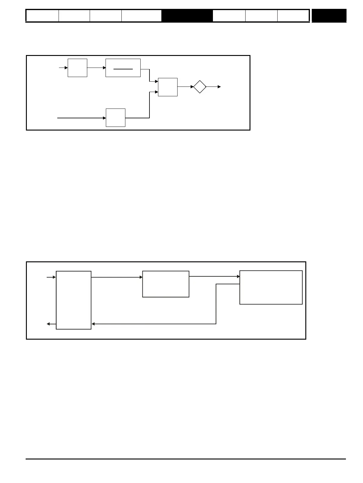
The diagram below shows how the variable selector in Sectional control mode can be used to provide a position reference for the drive and act as a
source for encoder simulation to give the position reference for the next drive in the system.
The input reference is provided by the previous drive in the system via the SM-Universal Encoder Plus module and is used as the position source
(Pr 12.08) for the variable selector. The destination of the variable selector is the local position reference for the menu 13 position controller
(Pr 13.21). Pr 13.21 counts up or down based on the delta position from the variable selector and rolls over or under at 65535 or 0. If the controller is
set up to ignore the local reference turns then Pr 13.21 can be used as the position controller reference. If Pr 13.21 is also used as the encoder
simulation source the local reference can also be used to give the reference for the next drive in the system. With this arrangement a ratio is provided
between the input reference and output reference within the variable selector. An addition ratio can be provided within the position controller between
the position in Pr 13.21 and the position reference used by the position controller. The variable selector speed reference can be used to move the
position reference forwards or backwards with respect to the input reference.
11. External Rectifier (SPMC/U) Monitor
This mode is intended to monitor an external rectifier system (SPMC/U) to provide over temperature monitoring, phase loss detection and mains loss
detection. The variable selector inputs should be routed to digital inputs on the drive or a Solutions Module, which are connected to the (SPMC/U)
rectifier status outputs. The external rectifier monitor produces a number of actions depending on the state of the inputs as given in the table below.
The ok state becomes active immediately both inputs are high, but the other states only become active when the required inputs have been active for
at least 0.5s. The high state is defined as a value greater than or equal to half the source maximum and the low state is defined as a value less than
half the source maximum (with the scaling parameters set to 1.000). If digital inputs are used as the sources and the scaling parameters are 1.000,
high is therefore defined as 1, and low is defined as 0. The variable selector output gives 0% if the rectifier is ok otherwise it gives 100%. The output
should be routed to Pr 6.51 (rectifier not active) so that the drive is not allowed to leave the main loss condition if the rectifier is not fully phased
forwards.
4.000 + 12.13
4.000
12.14
Σ
Position
input
Position
output
Speed
input
d/dt
Accumulator
Input
reference
Output
reference
SM-Universal
Encoder Plus
module
Source
Pr =Pr
12.08 x.05
mode
Destination
Pr = Pr
12.11 13.21
Menu 13 position controller
Reference source
Pr =Local(4)
Ignore local reference turns
Pr =1
13.04
13.24
Encoder simulation source
Pr = Pr
x.24 13.21