Parameter
structure
Keypad and
display
Parameter x.00
Parameter
description format
Advanced parameter
descriptions
Serial comms
protocol
Electronic
nameplate
Performance
Menu 1
Digitax ST Advanced User Guide 25
Issue Number: 1 www.controltechniques.com
*The range shown for Pr 1.07 shows the range used for scaling purposes (i.e. for routing to an analog output etc.). Further range restrictions are
applied as given below.
The same limits are applied to Pr 21.02, but based on the value of Pr 21.01.
(If the second motor map is selected Pr 21.01 is used instead of Pr 1.06 and Pr 21.02 instead of Pr 1.07)
The effects of the reference clamps (Pr 1.06 and 1.07), the negative minimum clamp enable (Pr 1.08) and the bipolar reference enable parameters
are defined below.
The variable maximum limit for reference parameters, SPEED_FREQ_MAX, is defined as:
If Pr 1.08 = 0: SPEED_FREQ_MAX = Pr 1.06
If Pr 1.08=1: SPEED_FREQ_MAX is Pr 1.06 or -Pr 1.07 whichever is the largest
(If the second motor map is selected Pr 21.01 is used instead of Pr 1.06 and Pr 21.02 instead of Pr 1.07)
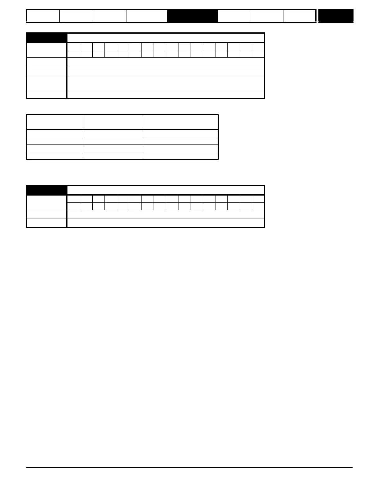
1.07 Minimum reference clamp
Coding
Bit SP FI DE Txt VM DP ND RA NC NV PT US RW BU PS
11 111
Range ±SPEED_LIMIT_MAX rpm*
Default 0.0
Second motor
parameter
Pr 21.02
Update rate Background read
Pr 1.08
(Neg min ref enable)
Pr 1.10
(Bipolar mode enable)
Range
0 0 0 to Pr 1.06
01 0
1 0 -SPEED_LIMIT_MAX to 0 rpm
1 1 -SPEED_LIMIT_MAX to 0 rpm
1.08 Negative minimum reference clamp enable
Coding
Bit SP FI DE Txt VM DP ND RA NC NV PT US RW BU PS
111
Default 0
Update rate Background read