Menu 3
Parameter
structure
Keypad and
display
Parameter x.00
Parameter
description format
Advanced parameter
descriptions
Serial comms
protocol
Electronic
nameplate
Performance
48 Digitax ST Advanced User Guide
www.controltechniques.com Issue Number: 1
Where:
Kc is the conversion between the speed controller output and the torque producing current. A value of unity at the output of the speed controller gives
a torque producing current equal to Kc. The drive automatically compensates the torque producing current for flux variations in field weakening, and
so Kc can be assumed to have a constant value even in field weakening. See menu 4 for the value of Kc each drive size).
Kt is the torque constant of the motor (i.e. torque in Nm per amp of torque producing current). This value is normally available for a servo motor from
the manufacturer, however for induction motors the value must be calculated from
Kt = Motor rated torque / Motor rated torque producing current
= Motor rated torque / √(Motor rated current
2
- No load current
2
)
L(s) is the transfer function of the load.
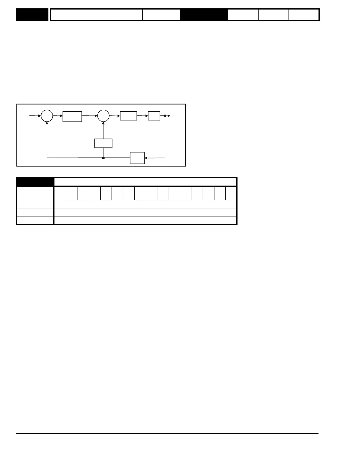
The s-domain system above may be used to determine the performance of systems with a relatively low bandwidth. However, the real drive system
also includes non-ideal delays due to the torque controller response, and speed measurement and control delays. These delays, which can be
approximated with a simple unity gain transport delay (T
delay
) as shown below, should be taken into account for more accurate results.
The user may enter the required speed controller gains into Pr 3.10 to Pr 3.15. However, if the load is predominantly a constant inertia and constant
torque, the drive can calculate the required Kp and Ki gains, provided a value of motor plus load inertia (Pr 3.18) and the motor torque per amp
(Pr 5.32) are set-up correctly. The gain values are calculated to give a required compliance angle or bandwidth. The calculated values for Kp and Ki
are written to Pr 3.10 and Pr 3.11 once per second when one of these set-up methods is selected (i.e. Pr 3.17 = 1 or 2). The values are calculated
from a linear model assuming a pure inertia load, not including unwanted delays in the speed and current controllers. The Kd gain is not affected. If
Pr 3.17 is set to 3 automatic gain set up is not active, but Kp is boosted by a factor of 16.
0: user set-up
With the default value the user should enter the required speed controller gains.
1: Bandwidth set-up
If bandwidth based set-up is required the following parameters must be set correctly: Pr 3.20 = required bandwidth, Pr 3.21 = required damping factor,
Pr 3.18 = motor + load inertia (it is possible to measure the load inertia as part of the auto-tuning process, see Pr 5.12 on page 81), Pr 5.32 = motor
torque per amp.
Ki = J / (Kc x Kt) x (2π x Bandwidth / Kbw)
2
= Pr 3.18 / (Kc x Pr 5.32) x (2π x Pr 3.20 / Kbw)
2
Where: Kbw = √[ (2ξ
2
+ 1) +√((2ξ
2
+ 1)
2
+ 1) ]
Kp = 2 ξ √ [(Ki x J) / (Kc x Kt)] = 2 ξ √ [(Pr 3.11 x Pr 3.18) / (Kc x Pr 5.32)]
2: Compliance angle set-up
If compliance angle based set-up is required the following parameters must be set correctly: Pr 3.19 = required compliance angle, Pr 3.21 = required
damping factor, Pr 3.18 = motor + load inertia (it is possible to measure the load inertia as part of the auto-tuning process, see Pr 5.12 on page 81),
Pr 5.32 = motor torque per amp.
Ki = 1 / Compliance angle (rad s
-1
)
Kp = 2 ξ √ [(Ki x J) / (Kc x Kt)] = 2 ξ √ [(Pr 3.11 x Pr 3.18) / (Kc x Pr 5.32)]
3: Kp gain times 16
If this parameter is set to 3 the Kp gain (from whichever source) is multiplied by 16. This is intended to boost the range of Kp for applications with very
high inertia. It should be noted that if high values of Kp are used it is likely that the speed controller output will need to be filtered (see Pr 4.12) or the
speed feedback will need to be filtered (see Pr 3.42). If the feedback is not filtered it is possible the output of the speed controller will be a square
wave that changes between the current limits causing the integral term saturation system to malfunction.
3.17
Speed controller set-up method
Coding
Bit SP FI DE Txt VM DP ND RA NC NV PT US RW BU PS
111
Range 0 to 3
Default 0
Update rate Background (1s) read
Kp+Ki/s
Ki.Kd
Kc.Kt L(s)
+
_
+
_
w*(s)
w(s)
T
delay