Menu 3
Parameter
structure
Keypad and
display
Parameter x.00
Parameter
description format
Advanced parameter
descriptions
Serial comms
protocol
Electronic
nameplate
Performance
50 Digitax ST Advanced User Guide
www.controltechniques.com Issue Number: 1
The hard speed reference is a reference value which does not pass through the ramp system (Menu 2). It is added to the normal post ramp speed
reference. Its value may be written from the keypad, via serial comms, from an analog input or from an encoder input. This parameter can also be
used by the position controller (Menu 13) as the speed reference input. The hard speed reference is selected when Pr 3.23 = 1.
The phase angle between the rotor flux in a servo motor and the encoder position is required for the motor to operated correctly. If the phase angle is
known it can be set in this parameter by the user. Alternatively the drive can automatically measure the phase angle by performing a phasing test (see
Pr 5.12 on page 81). When the test is complete the new value is written to this parameter. The encoder phase angle can be modified at any time and
becomes effective immediately. This parameter has a factory default value of 0.0, but is not affected when defaults are loaded by the user.
The alignment required for zero encoder phase angle (i.e. Pr 3.25 = 0.0) is given below for different feedback devices. Forward rotation of the motor
is produced when Vu leads Vv leads Vw. Although it is not essential, forward rotation of a motor is normally defined as clockwise when looking at the
motor shaft end. When the motor is rotating forwards the motor speed is shown as positive and the position increases.
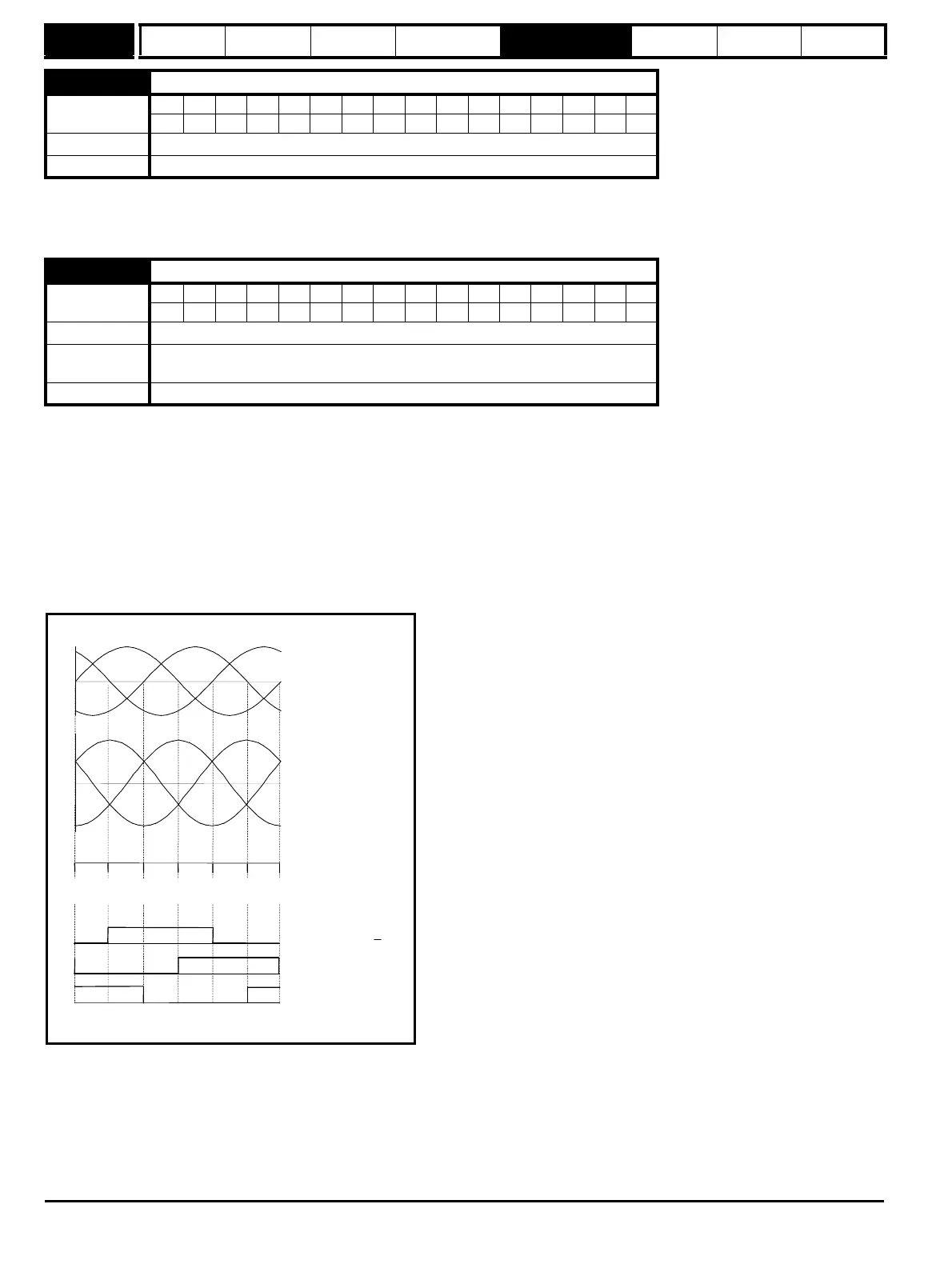
Encoder with commutation signals (Ab.Servo, Fd.Servo, Fr.Servo)
The alignment required between the no-load motor voltages and the commutation signals for Pr 3.25 = 0 is shown in the following diagram below:
It should be noted that if the encoder is advanced (i.e. the UVW signals are moved to the right with respect to the voltages) the phasing angle in
Pr 3.25 is increased from zero. If the encoder is retarded the phasing angle changes to 359.9° and then reduces towards zero.
3.23
Hard speed reference selector
Coding
Bit SP FI DE Txt VM DP ND RA NC NV PT US RW BU PS
111
Default 0
Update rate 4ms read
3.25
Encoder phase angle
Coding
Bit SP FI DE Txt VM DP ND RA NC NV PT US RW BU PS
11 111
Range 0.0 to 359.9 ° electrical
Second motor
parameter
Pr 21.20
Update rate Background read
Vwu
VvwVuv
Vw
Vv
Vu
No load phase
voltages
No load line
voltages
U Encoder commutation
signals (high = U > U)
V
W
Encoder alignment for zero encoder phase angle
Encoder angle 180
o
120
o
60
oo
0
o
300
o
240
o
180
32768 43691 54613 0 10923 21845 32768