Parameter
structure
Keypad and
display
Parameter x.00
Parameter
description format
Advanced parameter
descriptions
Serial comms
protocol
Electronic
nameplate
Performance
Menu 5
Digitax ST Advanced User Guide 87
Issue Number: 1 www.controltechniques.com
Pr 5.37 shows the actual switching frequency used by the inverter. The maximum switching frequency is set with parameter Pr 5.18, but this may be
reduced by the drive if automatic switching frequency changes are allowed (Pr 5.35=1). Pr 5.37 also indicates if the sample time for the current
controllers have been reduced to allow for SINCOS encoders with lines per revolution that are not a power of two.
By applying short current pulses to the motor and using the resulting movement the drive can calculate the phasing angle (Pr 3.25 or Pr 21.20). These
begin at as short low level pulses, which are increased in magnitude and length until the required electrical movement define by Pr 5.38 is achieved.
The actual movement may be larger because motor cogging may cause additional unwanted movement. The required movement should only be
reduced if this is necessary as the results become less accurate with less movement. Care should be taken to ensure that the minimum movement is
large enough so that the change of position given by the feedback device can be registered by the drive. For example a 4096 line incremental device
on a 6 pole motor will give a change of position count of 75 for a 5°electrical movement. It is suggested that this test should not be used with a change
of position count of less than 50. Although Pr 5.38 can be reduced to zero the lowest value used by the drive is 1.0 degrees.
The necessary movement can be produced with a lower torque level if the test pulses are extended. If the pulses of torque are smaller then the
acceleration is less, and so the noise and vibration produced by the test are less. The pulse length can be modified with Pr 5.39 (1 = pulse lengths x
2, 2 = x 3, and 3 = x 4). Longer pulses should only be used if noise and vibration are a problem and the motor has low friction and low cogging torque.
As the torque level is reduced the measurement is likely to be affected by cogging and the results may not be accurate.
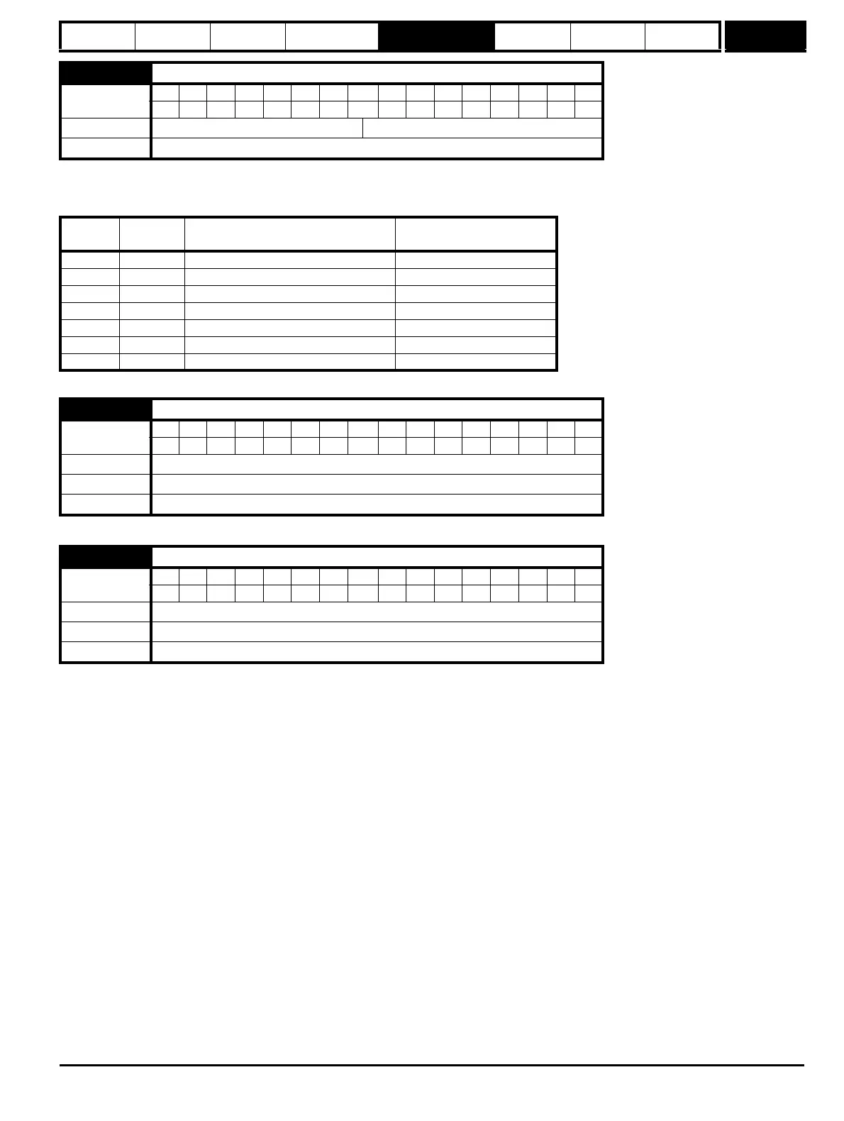
5.37 Actual switching frequency
Coding
BitSP FI DETEVMDPNDRANCNVPTUSRWBUPS
11111
Range 0 to 7
Update rate
Background write
Value String Switching frequency (kHz)
Current controller Sample
time (us)
03 3 167
14 4 125
26 6 83
38 8 125
412 12 83
66 rEd 6 167
7 12 rEd 12 167
5.38 Minimal movement phasing test angle
Coding
BitSP FI DETEVMDPNDRANCNVPTUSRWBUPS
1111
Range 0 to 25.5 degrees
Default 5.0 degrees
Update rate
Background read
5.39 Minimal movement phasing test pulse length
Coding
BitSP FI DETEVMDPNDRANCNVPTUSRWBUPS
111
Range 0 to 3
Default 0
Update rate
Background read