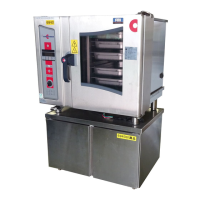
Connecting up the combi steamer
Installation manual 60
Gas installation components
The table below shows the components required for a standards-compliant gas installation:
Component Description
Fixed connection
The appliance is designed to be permanently connected to the customer's gas
supply. Position of the gas supply: point J in the connection diagram.
Gas shut-off device
A gas shut-off device must be fitted close to the appliance. The gas shut-off device
must be easily accessible, and situated so that it can also be shut off in case of
danger.
Pressure reducer
A pressure reducer must be fitted if the supply flow pressure is too high.
All connection compo-
nents
All connection components provided by the customer must be tested in accordance
with local and national regulations.
Installing the gas supply
Follow the steps below to provide the gas supply for your combi steamer:
Step Action
1
Measure the supply flow pressure.
2 Compare the type of gas, the gas pressure and the rating for the gas supply connection with the data
given on the appliance type plate.
3
Fit a pressure reducer if the supply flow pressure is too high.
4
Connect the gas supply.
5 Check that all connections inside and outside the appliance are sealed (e.g. using gas detector or
leak locator spray).
Caution
Do not spray leak locator spray on the flame-monitor electrical leads.
6
Inform the user that the gas components must be serviced annually.
7 Check the flue-gas values against the figures given in the "Gas valve installation instructions" held in
the wiring compartment.
Carry out a flue gas analysis.
Check that the analysis values lie within the permitted flue gas values given in the table above.
Record the measurements in the appliance.
8
Once the gas installation is finished, close the gas shut-off device.
Flue gas value records
You can use the table below to keep records of flue gas values:
O
2
λ
CO
2
CO Gas type
[%]
[%] [ppm]
 Loading...
