NetworkingNetworking
Network CableNetwork Cable
Up to One Hundred & Twenty Six Panels or repeaters can be networked together to
operate as a single networked system. To achieve this each panel must be fitted with a
network card (Optional Extra)
When operating as a networked system all fire and fault event information is displayed
at every panel, silencing and resetting of alarms can also be carried out from any panel
on a networked system if panels are suitably configured.
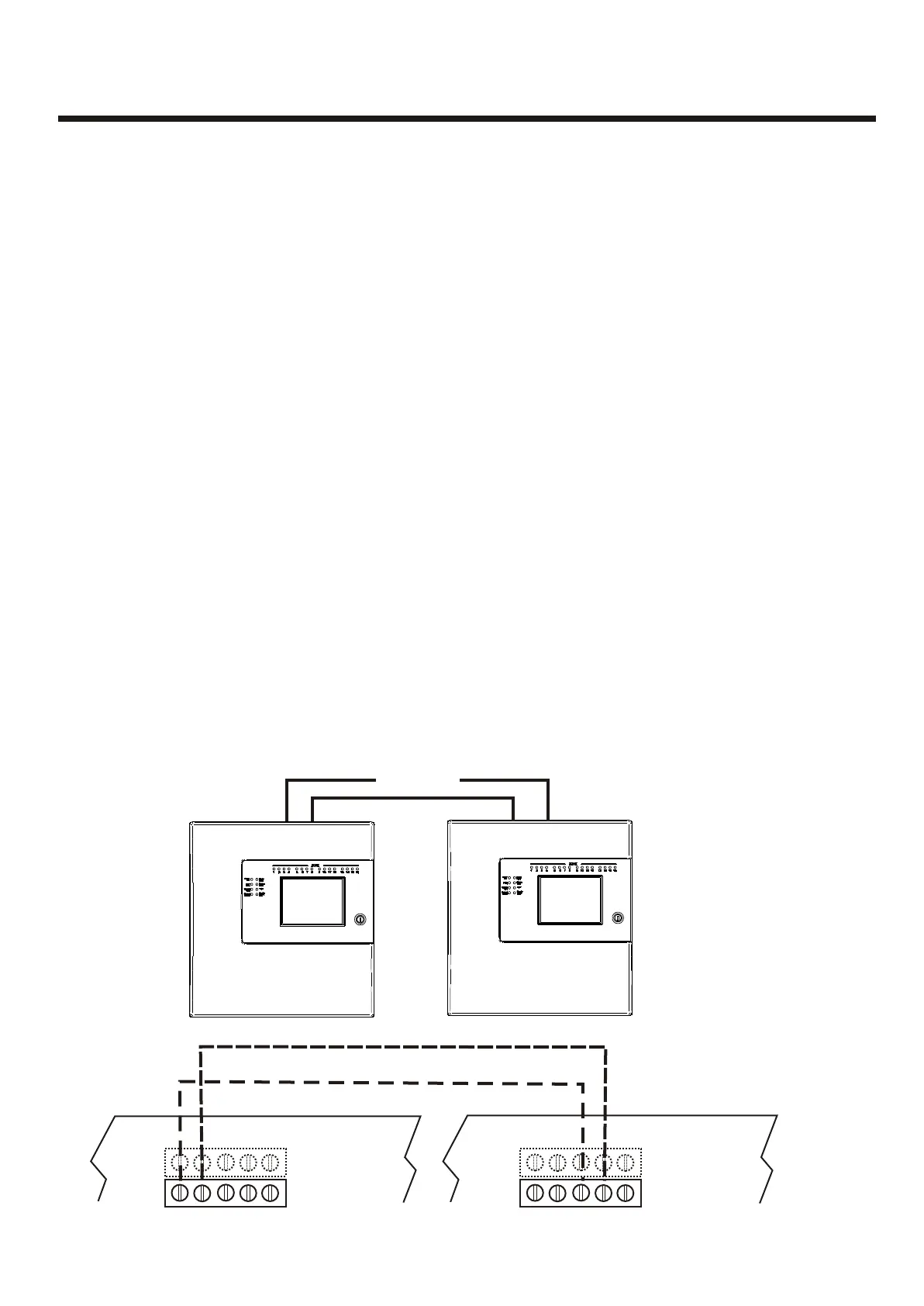
Networked panels are connected using a loop topology as illustrated.
Networked panels can be used as active repeaters, alternatively a low cost passive
repeater is available.
This can either be connected a loop of an individual panel or it can be connected to the
network.
The recommended network cable for the network connection between panels is an
enhanced Firetuf cable Manufactured by Draka cables (part number )910234.
Screen continuity must be maintained throughout the entire network circuit including at
each junction point. The screen should only be earthed at the connection point provided
at the first panel and not at any other point. The screen or drain wire of the network
cable should not be considered as a safety earth and therefore should not be connected
to terminals marked with the earth symbol, except at the panel, and should not be
insulated with green and yellow sleeving
Where the network cable passes between buildings, screen continuity should not be
maintained from building to building. A booster device must however be used
irrespective of cable length and should be fitted at a suitable point in the link between
buildings. The cable screen should be connected to the earth of one panel in each
building. 102 S terminator should be fitted at the beginning and the end of the network.
If the distance in the network exceeds 1KM the booster should be used. The booster
requires 24V local supply, which can be connected to nearest Addressable Panel
Up to One Hundred & Twenty Six Panels or repeaters can be networked together to
operate as a single networked system. To achieve this each panel must be fitted with a
network card (Optional Extra)
When operating as a networked system all fire and fault event information is displayed
at every panel, silencing and resetting of alarms can also be carried out from any panel
on a networked system if panels are suitably configured.
Networked panels are connected using a loop topology as illustrated.
Networked panels can be used as active repeaters, alternatively a low cost passive
repeater is available.
This can either be connected a loop of an individual panel or it can be connected to the
network.
The recommended network cable for the network connection between panels is an
enhanced Firetuf cable Manufactured by Draka cables (part number 910234 )
Screen continuity must be maintained throughout the entire network circuit including at
each junction point. The screen should only be earthed at the connection point provided
at the first panel and not at any other point. The screen or drain wire of the network
cable should not be considered as a safety earth and therefore should not be connected
to terminals marked with the earth symbol, except at the panel, and should not be
insulated with green and yellow sleeving
Where the network cable passes between buildings, screen continuity should not be
maintained from building to building. A booster device must however be used
irrespective of cable length and should be fitted at a suitable point in the link between
buildings. The cable screen should be connected to the earth of one panel in each
building. 102 terminator should be fitted at the beginning and the end of the network.
If the distance in the network exceeds 1KM the booster should be used. The booster
requires 24V local supply, which can be connected to nearest Addressable Panel
.
S
23
TOPTOP
BB
XX
EE
YY
AATOPTOP
BB
XX
EE
Network Terminal
on main PCB
(Panel 2)
Network Terminal
on main PCB
(Panel 2)
YY
AA
Network Terminal
on main PCB
(Panel 1)
Network Terminal
on main PCB
(Panel 1)