DB Level Check
Panel includes the facility to test and set the system sounders with the minimum amount
of disturbance. In sounder test mode, the sounders will sound for 30 seconds on then
30 seconds off. This facility can be accessed via the engineering menu.
Detector LED Flashing
The Panel Sensor flashing function is used to allow a visual inspection and confirmation
that the fire panel is in communication with the installed system devices. This facility can
be accessed via the engineering menu and can be switched on or off at any time as
required.
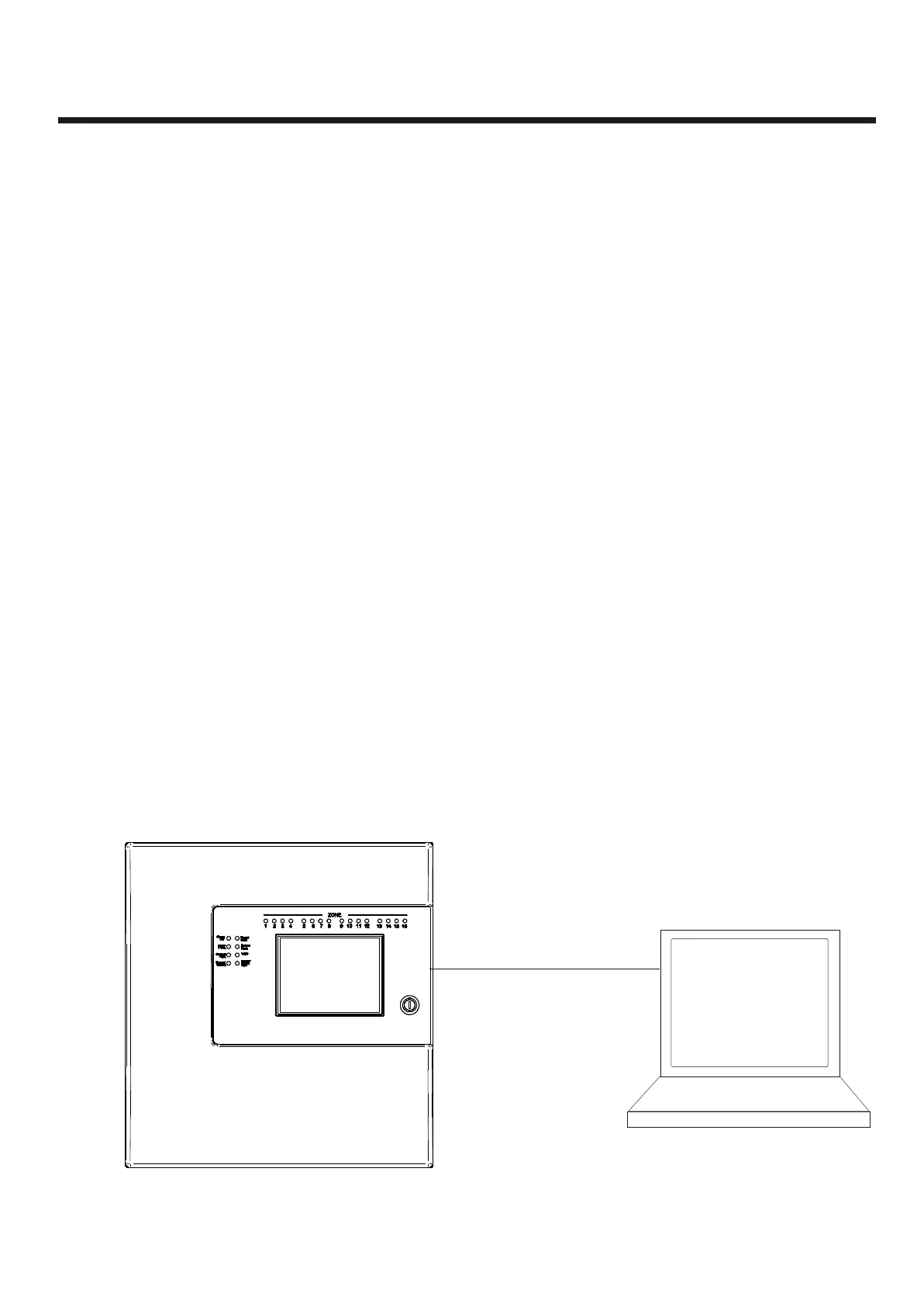
Up/downloading using PC Software
The PC Software enables the address, location text, device type and any comments to
be downloaded to the panels.
The software can download to all 126 networkable Panels.
The PC is connected to each Panel on the network in turn. All data for the Panel is
downloaded.
For networked systems, panels are identified by panel number, P1, P2 etc.
DB Level Check
Detector LED Flashing
Up/downloading using PC Software
Panel includes the facility to test and set the system sounders with the minimum amount
of disturbance. In sounder test mode, the sounders will sound for 30 seconds on then
30 seconds off. This facility can be accessed via the engineering menu.
The Panel Sensor flashing function is used to allow a visual inspection and confirmation
that the fire panel is in communication with the installed system devices. This facility can
be accessed via the engineering menu and can be switched on or off at any time as
required.
The PC Software enables the address, location text, device type and any comments to
be downloaded to the panels.
The software can download to all 126 networkable Panels.
The PC is connected to each Panel on the network in turn. All data for the Panel is
downloaded.
For networked systems, panels are identified by panel number, P1, P2 etc.
ConfigurationConfiguration
29
Null Modem Cable
A.serial Output
B. USB Output
Via
USB Convertor
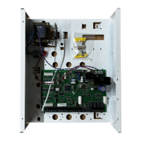
Serial Rs232 port can be
locatated on the main board