92
Security House,
Vantage Point Business Village,
Mitcheldean,
Glos. GL17 0SZ
Tel: 01594 541900
www.cooperfire.co.uk
Installation Guide for
Spur Isolator Unit
CSI350
CSI350 - Specification:
Installation:
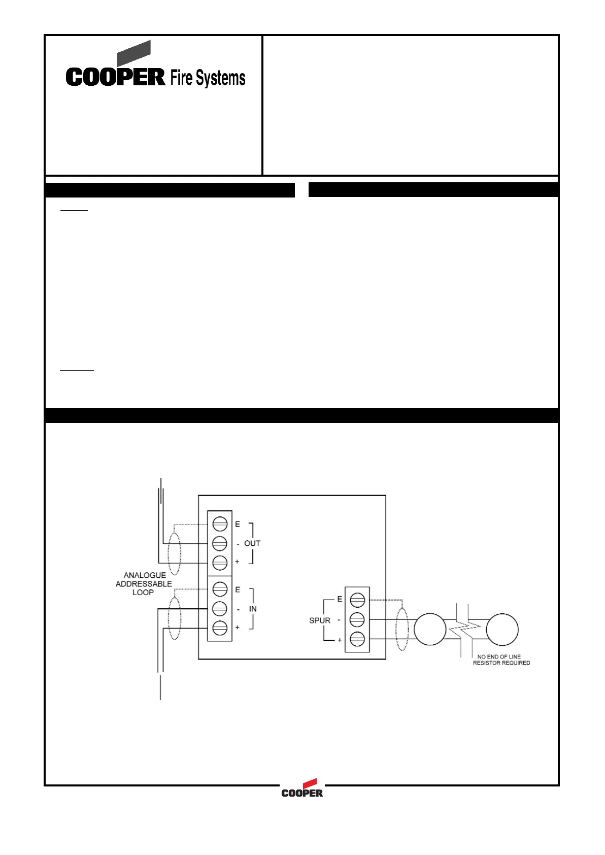
Wiring Schematic:
DOC. REF.: PINSTCSI350
Notes:
1. Cable earth screen must be connected to its adjacent earth terminal.
2. For maximum spur length/load see BS5839 Pt1:2002
3. This unit can only be used with Cooper Fire Systems CAB300 sensor bases and compatible sensors
Wiring
Each unit terminal connector is suitable for clamping a
single cable conductor up to a maximum of 2.5mm².
The CSI350 unit is suitable for mounting on to back boxes
with 120mm fixing centres. (surface mounting box supplied)
General
Addressing of the unit is not required (see control panel
operation for details)
170µA
-10 to +60C
0 to 95% non condensing
IP40
EN54:Pt 2 and 4
BS5839:Pt 1 (installation)
CE Marked
PC\ABS
147(w)x88(h)x57(d) mm
0.5 to 2.5mm²
Draka - FIRETUF
Pirelli - FP200
MICC
170µA
-10 to +60C
0 to 95% non condensing
IP40
EN54:Pt 2 and 4
BS5839:Pt 1 (installation)
CE Marked
PC\ABS
147(w)x88(h)x57(d) mm
0.5 to 2.5mm²
Draka - FIRETUF
Pirelli - FP200
MICC
Quiescent Current:
Operating Temperature:
Humidity:
IP Rating:
Standards:
EMC:
Materials:
Dimensions:
Cable Size (Min-Max:)
Recommended Cable Types:
Quiescent Current:
Operating Temperature:
Humidity:
IP Rating:
Standards:
EMC:
Materials:
Dimensions:
Cable Size (Min-Max:)
Recommended Cable Types:
1 Separate the two halves of the unit
2 Drill out the required holes for cable entries
3 Mount the back box in the required position
4 Install wiring through the pre-drilled holes
5 Connect the unit as per diagram below
6 Fit front cover
1 Separate the two halves of the unit
2 Drill out the required holes for cable entries
3 Mount the back box in the required position
4 Install wiring through the pre-drilled holes
5 Connect the unit as per diagram below
6 Fit front cover