being unloaded will minimize heat loss from the discharge
line for the best liquid transfer rate.
Unloading stationary tanks with a compressor is quite
practical. Delivery trucks and other large containers can
be filled rapidly if the vapor system of the tank to be
filled will permit fast vapor withdrawal, and if the liquid
piping system is large enough. Many older trucks (and
some new ones) are not originally equipped with vapor
excess flow valves large enough to do a good job and
these should be replaced by a suitable size valve. The
liquid discharge should be connected to the tank truck
pump inlet line rather than the often oversized filler valve
connection in the tank head.
It is of extreme importance to prevent the entry of
liquid into the compressor. The inlet of the compressor
should be protected from liquid entry by a liquid trap
(see section 2.4). It is of equal importance to protect the
discharge of the compressor from liquid. This may be
done by installing a check valve on the discharge and
designing the piping so liquid cannot gravity-drain back
into the compressor. Make sure to install a check valve
on vapor lines discharging to the liquid space of the tank.
All piping must be in accordance with the laws and codes
governing the service. In the United States, the following
codes apply:
For LP-Gas — The National Fire Protection Association
Pamphlet No. 58, Standard for the Storage and Handling
of Liquefied Petroleum Gases.
For Ammonia — The American National Standards
Institute, Inc., K61.1-1999, Storage and Handling of
Anhydrous Ammonia.
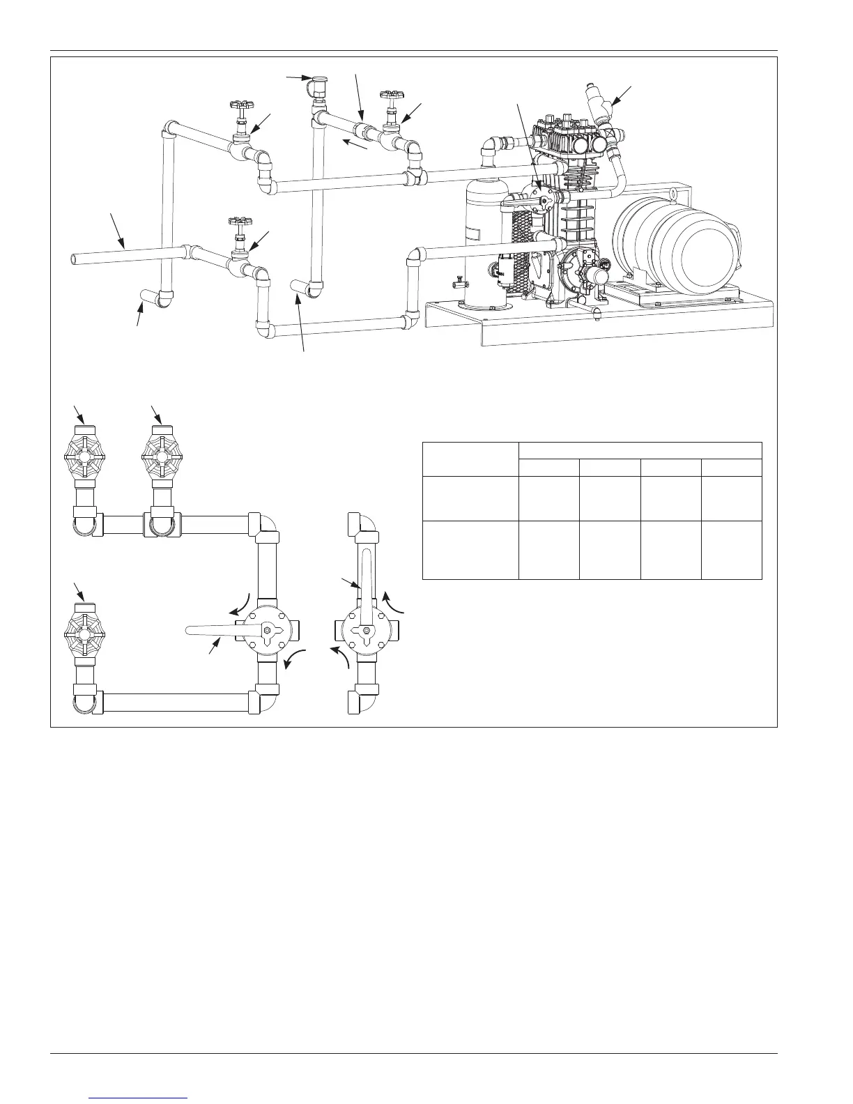
Back check valve
Hydrostatic releif valve
A
B
C
Vapor line rail car
(in-bound
bulk transfer)
Bury or insulate in
cold climate areas
4-Way valve
Relief valve
Vapor line to gas
phase in storage
Vapor line to liquid
phase in storage
4-Way Valve
Position 1
B
4-Way Valve
Position 2
Service to
Perform
Valve Position
4-way A B C
1. Unload
tank car into
storage tank
Position
One
Open Open Close
2. Recover
vapors from
tank car into
storage tank
Position
Two
Close Open Open
4-way Valve Operation
Figure 2.3C: Three valve manifold piping system.
10