Disassembly
1. Unscrew the valve cap/nut and remove the O-ring
from the coverplate.
2. Remove the valve cover plate, O-ring and holddown
screw by removing each of the four bolts. NOTE:
Since the holddown screw has been secured with an
impact wrench at the factory, you will probably need
to wait to remove the holddown screw until after the
cover plate has been removed. At this point in time,
the holddown screw can be easily removed from the
cover plate. The holddown screw on model 691 and
891 is most easily removed with the special wrench
supplied with your compressor at time of purchasing.
3. After the cover plate and O-ring have been removed,
the valve spacer (model 491 only), valve cage, valve
assembly and valve gasket can be lifted out.
4. Inspect valves for breakage, corrosion, debris,
and scratches on the valve plate. In many cases,
valves may simply be cleaned and reinstalled. If the
valves show any damage, they should be repaired or
replaced. Replacement is usually preferable although
repair parts are available. If valve plates are replaced,
seats should also be lapped until they are perfectly
smooth. If more than .005 in. must be removed
to achieve a smooth surface, the valve should be
discarded. If plates are replaced without relapping the
seat, rapid wear and leakage may occur.
Assembly
1. Insert metal valve gasket into the suction and/or
discharge opening of the head. The metal valve gasket
should always be replaced when the valve is reinstalled.
2. Insert cleaned or new valve assembly. Make sure the
suction and discharge valves are in the proper suction
and discharge opening in the head.
3. Insert the valve cage and valve spacer (NOTE: spacer
applies to model 491 compressor only).
4. Replace the O-ring and valve cover plate. Torque
bolts to the value listed in Appendix B. CAUTION: Be
sure the holddown screw has been removed.
5. Insert the holddown screw and tighten to the value
listed in Appendix B to ensure the valve gasket is
properly seated. NOTE: Gaskets and O-rings are not
normally reusable.
6. Replace the O-ring (or gasket) and valve cap/nut and
tighten to the value listed in Appendix B. O-rings
sealing the valve cap should be replaced if they show
signs of wear or damage. Valve caps sealed by flat
metals gaskets should be reinstalled with new gaskets.
7. NOTE: The Model 491 Spec 3 suction valve has an
adjusting screw to set the liquid relief pressure. To set
the liquid relief pressure, the screw bottom must be
tightened to 1.8" from the top of the valve body.
8. Check bolts and valve holddown screws after first
week of operation. Re-torque if necessary. See
Appendix B for torque values.
5.2 Heads
A compressor head very seldom requires replacement
if the compressor is properly maintained. The primary
cause of damage to a head is corrosion and the entry
of solid debris or liquid into the compression chamber.
Improper storage can also result in corrosion damage to
the head (for proper storage instructions see chapter 6).
Many compressor repair operations require removal of the
head. While the compressor is disassembled, special care
should be taken to avoid damage or corrosion to the head. If
the compressor is to be left open for more than a few hours,
bare metal surfaces should be coated with rust preventative.
When reassembling the compressor, make sure the bolts
are retightened as shown in Appendix B.
5.3 Piston Rings and Piston Ring
Expanders
Piston ring life will vary considerably from application to
application. Ring life will improve dramatically at lower
speeds and temperatures.
1. To replace the piston rings, depressurize the
compressor and purge if necessary.
2. Remove the head to gain access to the compressor
cylinder.
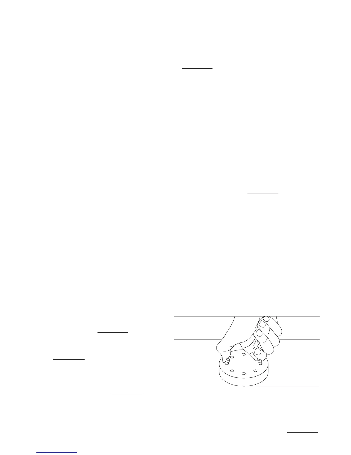
3. Loosen the piston head bolts. Remove the piston as
shown in figure 5.3A by pinching two loose bolts together.
Figure 5.3A: Piston removal
4. Piston rings and expanders may then be easily
removed and replaced. Corken recommends replacing
expanders whenever rings are replaced. To determine
if rings should be replaced, measure the radial
thickness and compare it to the chart in Appendix C.
20