2.8 Truck Mounted Compressors
Corken compressors may be mounted on trucks to perform
liquid transfer operations as described in section 1.1. The
compressor should be mounted so the inspection plate is
accessible for packing adjustment. The compressor must
be protected against liquid as explained in section 2.4
and a relief valve must be installed in the discharge piping
before the first downstream shutoff valve.
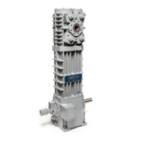
Three types of mountings are typically used. The inside
mounting (figure 2.8A) drives the compressor directly off
the PTO shaft. The PTO must be selected to drive the
compressor between 400 and 800 RPM. An extended
compressor crankshaft is required so the U-joint yoke
may connect to the compressor without removing the
flywheel. Do not operate the compressor without a
flywheel. Use a U-joint with a splined joint and make sure
the connections are parallel and in line. The U-joint angle
should be less than 15 degrees (see figure 2.8B). Always
use an even number of U-joints.
Figure 2.8A: Inside transport mounting.
Figure 2.8B: U-joint drive for compressor.
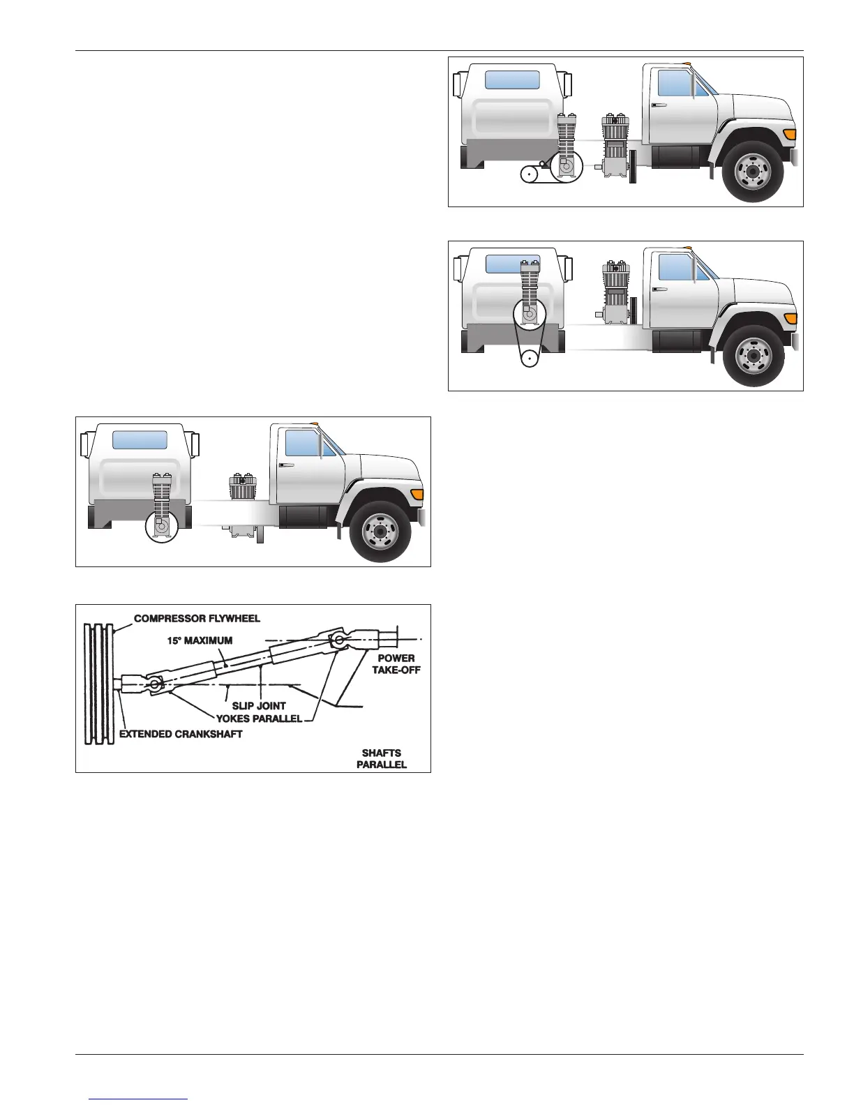
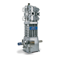
Depending on the truck design, the compressor may be
outside or top mounted as shown in figures 2.8C and
2.8D to be V-belt driven. Power is transmitted through
a U-joint drive shaft, jackshaft with two pillow block
bearings, V-belt sheave and V-belts. An idle pulley may
be used under the truck frame.
Figure 2.8C: Outside transport mounting
Figure 2.8D: Top transport mounting.
2.9 Shutdown/Alarm Devices
For many applications, shutdown/alarm switches will
provide worthwhile protection that may prevent serious
damage to your compressor system. All electronic
devices should be selected to meet local code
requirements. Shutdown/alarm devices typically used on
Corken compressors are as follows:
1. Low Oil Pressure Switch: Shuts down the unit if
crankcase oil pressure falls below 12 psi due to oil
pump failure or low oil level in crankcase. The switch
or the compressor controller must have a 30 second
delay on startup which allows the compressor to
build oil pressure in the crankcase.
2. High Discharge Temperature Switch: This switch
is strongly recommended for all applications. Both
the High Discharge Temperature switch (HDT) and
compressor have an operating pressure range. It is
preferable that the switch set point be midpoint in its
range and 30°F (-1°C) above the normal discharge
temperature, but below the maximum design
temperature for the compressor of 350°F (176.7°C).
3. Low Suction Pressure Switch: Shuts down the
unit if inlet pressure is not within the preset limit (set
point). In some cases, it is important not to pull a
vacuum because of the potential of pulling oil from the
crankcase into the gas stream.
4. High Discharge Pressure Switch: Shuts down the
unit if the outlet pressure reaches a preset limit (set
point). Both the switch and the compressor have an
operating range. The set point of the pressure switch
should be as follows:
15