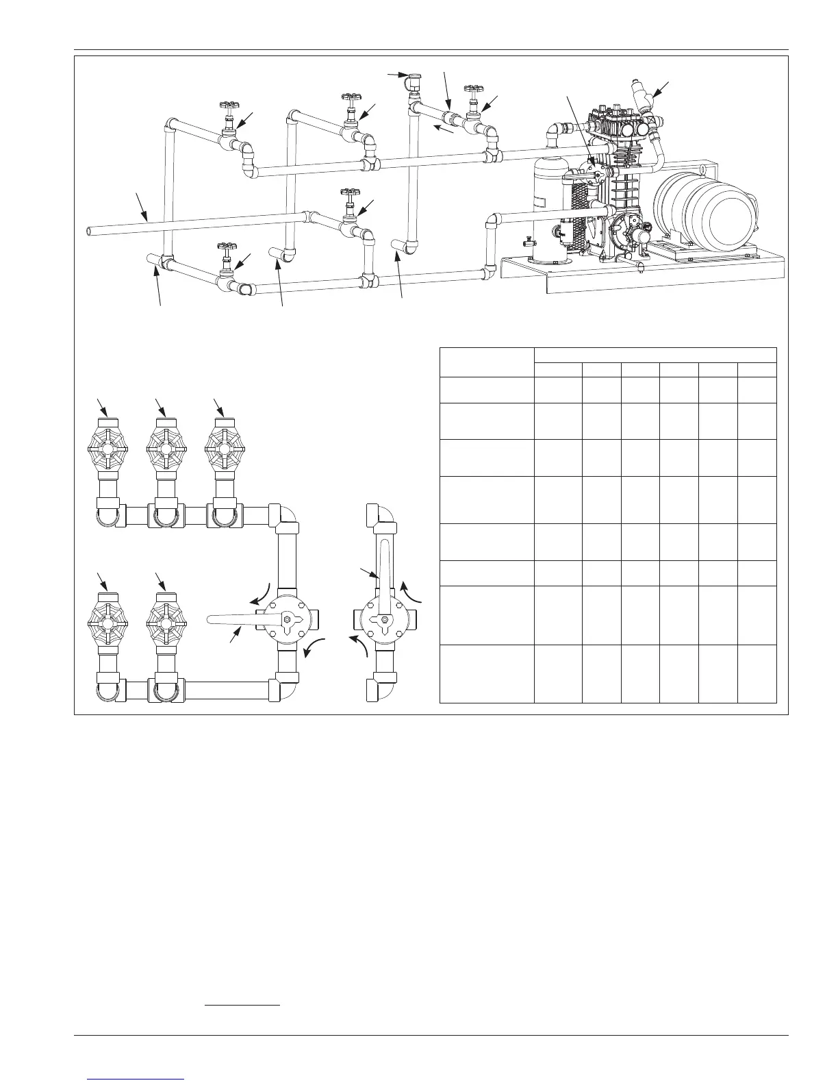
107 style compressors are usually connected using a five-
valve (figure 2.3B) or three-valve manifold (figure 2.3C).
The five-valve manifold allows the storage tank to be
both loaded and unloaded. The three-valve manifold only
allows the storage tank to be loaded. Adequate sizing of
the liquid and vapor lines is essential to limit the pressure
drop in the system to a reasonable level (20 psi or less).
The line size helps determine the plant capacity almost
as much as the size of the compressor, and liquid line
sizes are a bigger factor than vapor lines. If the pressure
gauges on the head indicate more than a 15 to 20 psi
(1.0 to 1.4 bars) differential between the inlet and outlet
pressures, the line sizes may be too small or there is too
much piping restriction. The less restriction in the piping,
the better the flow. Appendix C shows recommended
pipe sizes for typical LPG/NH
3
compressor installation.
A tank car unloading riser should have two liquid hoses
connected to the car liquid valves. If only one liquid
hose is used, the transfer rate will be slower and there
is a good possibility that the car’s excess flow valve
may close.
Since the heat of compression plays an important part in
rapid liquid transfer, the vapor line from the compressor to
the tank car or other unloading container should be buried
or insulated to prevent the loss of heat and the compressor
should be located as near as possible to the tank being
emptied. In extremely cold climates, if the line from the
storage tank to the compressor is over 15 feet (4.6 meters)
long, it should be insulated to lessen the possibility of
vapors condensing as they flow to the compressor. The
vapor recovery discharge line should not be insulated.
Placing the compressor as close as possible to the tank
Hydrostatic relief valve
Back check valve
Relief valve
4-Way valve
C
Vapor line to liquid phase
in storage tank
B
Vapor line to truck
trailer or tank
(local transport)
Vapor line to
rail car
(inbound bulk
transport)
Vapor line to gas phase
in storage tank
D
E
A
Bury or
insulate in
cold climate
areas
4-Way Valve
Position 1
E B
4-Way Valve
Position 2
Service to Perform
Valve Position
4-way A B C D E
1. Unload tank car
into storage tank
Position
One
Open Open Close Close Close
2. Recover vapors
from tank car into
storage tank
Position
Two
Close Open Open Close Close
3. Unload transport
or truck into
storage tank
Position
One
Open Close Close Close Open
4. Recover vapors
from transport or
truck into storage
tank
Position
Two
Close Close Open Close Open
5. Load truck or
field tank from
storage tank
Position
Two
Open Close Close Close Open
6. Load truck or field
tank from tank car
Position
One
Close Open Close Open Close
7. Equalize between
tank car and
storage tank
without using
vapor pump
— Open Open Close Open Open
8. Equalize between
truck or field tank
and storage tank
without using
vapor pump
— Open Close Close Open Close
4-way Valve Operation
Figure 2.3B: Five valve manifold piping system.
9