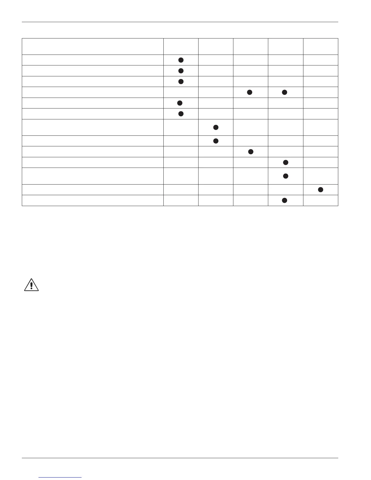
Item to Check Daily Weekly Monthly
Six
Months
Yearly
Crankcase oil pressure
Compressor discharge pressure
Overall visual check
Crankcase oil level
1 1
Drain liquid from accumulation points
2
Drain distance pieces
Clean cooling surfaces on compressor and
intercooler (if any)
Lubricator supply tank level (if any)
Check belts for correct tension
Inspect valve assemblies
Lubricate motor bearings in accordance with
manufacturers’ recommendations
Inspect motor starter contact points
Inspect piston rings
1
3
Chapter 4—Routine Maintenance Chart
1
Change oil every 2,200 hours of operation or every 6 months, whichever occurs first. If the oil is unusually dirty, change it as often as needed to maintain a
clean oil condition. Change replacement filter 4225 with every oil change.
2
Liquid traps should be drained prior to startup.
3
Piston ring life varies greatly, depending on application, gas, and operating pressures. Consult factory for additional recommendations for your specific
application.
Chapter 5—Routine Service and
Repair Procedures
CAUTION: Always relieve pressure in the unit
before attempting any repairs. After repair,
the unit should be pressure tested and checked for
leaks at all joints and sealing surfaces.
If routine maintenance is performed as listed in chapter
4, repair service on your Corken gas compressor is
generally limited to replacing valves or piston rings.
When it comes time to order replacement parts, be sure
to consult the part details appendix in the back of this
Installation, Operation & Maintenance (IOM) manual for a
complete list of part numbers and descriptions.
5.1 Valves
Test the compressor valves by closing the inlet piping
valves while the unit is running; however, do not allow
the machine to operate in this way very long. If the
inlet pressure gauge does not drop to zero almost
immediately, one or more of the valves is probably either
damaged or dirty. It is possible, of course, that the
pressure gauge itself is faulty.
Inspect valves for breakage, corrosion, debris, and
scratches on the valve disc. In many cases, valves may
simply be cleaned and reinstalled. If the valves show
any damage, they should be repaired or replaced.
Replacement is usually preferable, although individual
parts are available. If valve discs are replaced, seats
should also be lapped until they are perfectly smooth.
A maximum of .005 inch can be removed during the
lapping process. If more than .005 inch must be removed
to achieve a smooth surface, the valve should be
discarded. If discs are replaced without relapping the
seat, rapid wear and leakage may occur.
Each suction and/or discharge valve assembly is easily
removed as a unit for inspection. If any part of the valve
assembly is broken, the valve assembly should be replaced.
See valve assembly parts details in the appendices for a
complete list of part numbers and descriptions.
If a valve is leaking due to dirt or any other foreign
material that keeps the valve plate and seat from sealing,
the valve may be cleaned and reused. New gaskets and/
or O-rings should be used to assure a good seal.
The valve holddown assemblies and valve assemblies on
the following pages show the various specifications used
on models 91, 291, 491, 691 and 891 compressors. Since
more than one suction valve arrangement is available for
each model of compressor, it is necessary to know your
complete model number so you can identify the valve
18