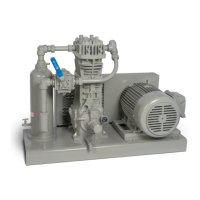
109 and 107 compressor mountings (see Appendix D for
details on standard Corken compressor mountings).
When the compressor will not be under more-or-less
constant observation an automatic trap is recommended.
The automatic trap replaces the float with electrical float
switches. If the liquid level should rise too high, the level
switch will open and disconnect the power to the motor
starter, stopping the compressor. This design ensures
the machine will be protected even when it is not under
close observation and is standard in the 109A and 107A
mounting configurations.
Corken’s most sophisticated trap provides the most
thorough liquid separation. This trap is larger and is
ASME code stamped. It contains two level switches, one
for alarm and one for shutdown. In some cases the alarm
switch is used to activate a dump valve (not included
with trap) or sound an alarm for the trap to be manually
drained by the operator. This trap also contains a mist
pad. A mist pad is a mesh of interwoven wire to catch fine
liquid mists. The ASME code trap is standard in the 109B
and 107B mounting configurations.
A typical wiring diagram for the liquid level switch is
shown in figure 2.4B.
Install, use and maintain this equipment according to
Corken instructions and all applicable federal, state, and
local laws and previously mentioned codes.
2.4 Liquid Traps
Compressors are designed to pressurize gas, not to pump
liquids. The entry of even a small amount of liquid into the
compressor will result in serious damage to the compressor.
On liquefied gas applications, a liquid trap must be used
to prevent the entry of liquid into the compressor.
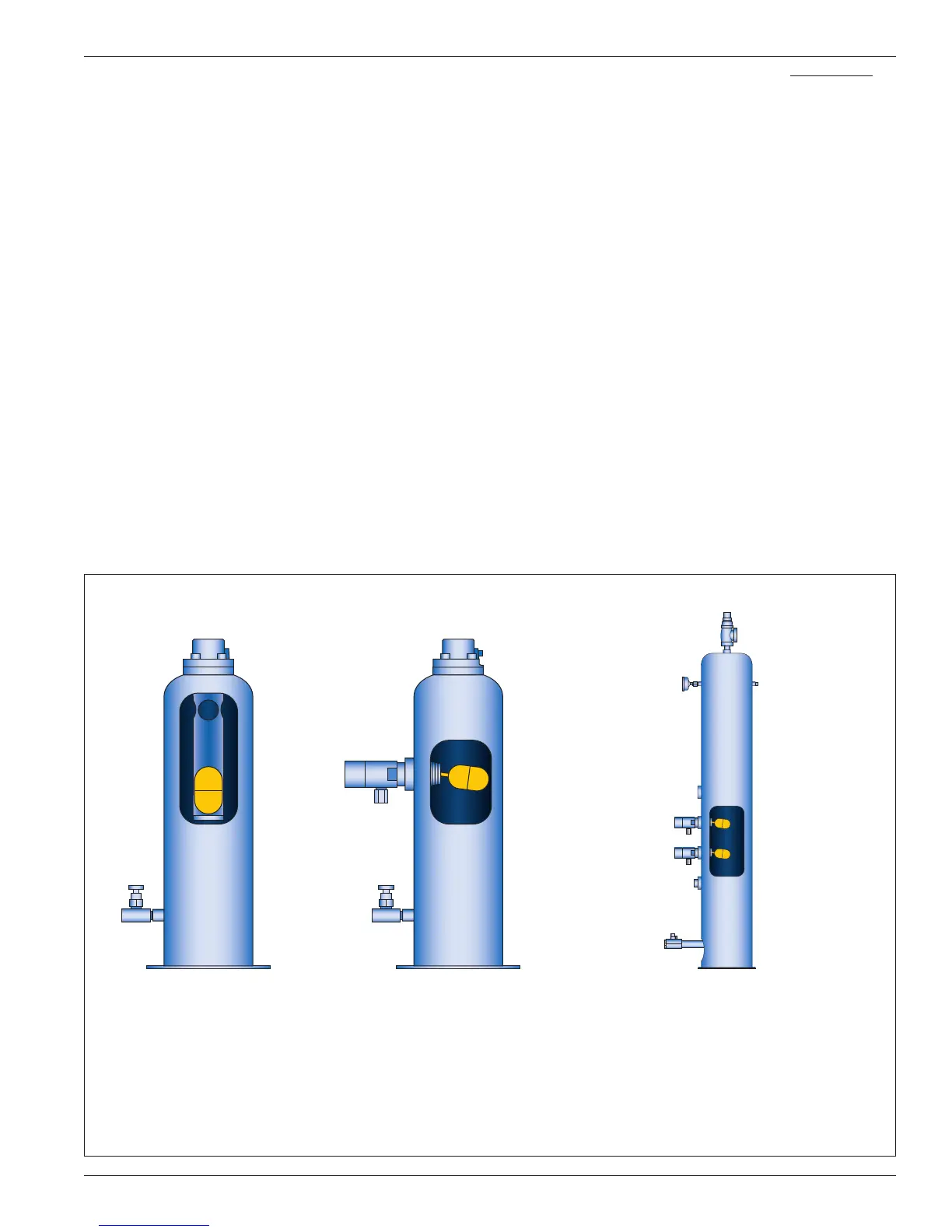
Corken offers three types of liquid traps for removal of
liquids in the gas stream (see figure 2.4A). The simplest is
a mechanical float trap. As the liquid enters the trap the
gas velocity is greatly reduced, which allows the liquid
to drop out. If the liquid level rises above the inlet, the
float will plug the compressor suction. The compressor
creates a vacuum in the inlet piping and continues to
operate until the operator manually shuts it down. The
trap must be drained and the vacuum-breaker valve
opened before restarting the compressor, to allow the
float to drop back. This type of trap is only appropriate
for use where the operator keeps the compressor under
fairly close observation. This trap is provided with the
Figure 2.4A: Liquid traps.
Standard liquid trap with
mechanical float assembly
and drain valve.
Sizes: • 1-1/4" x 1-1/4" NPT
• 1-1/4" x 1-1/2" NPT
Automatic liquid trap, with one
NEMA 7 liquid-level switch for
compressor shutdown and
drain valve.
Sizes: • 1-1/4" x 1-1/4" NPT
• 1-1/4" x 1-1/2" NPT
Class 300 RF flange code-stamped
automatic liquid trap with two NEMA 7 liquid-
level switches for compressor shutdown and
alarm. Equipped with relief valve, pressure
gauge, demister pad, and drain valve.
Sizes: • 1-1/2" x 1-1/2" NPT
• 2" x 2" Class 300 RF flange
Standard Liquid Trap Automatic Liquid Trap ASME Automatic Liquid Trap
11