5
1
9
4
2
5
8
6
3
2
Note
alignment
marks
7
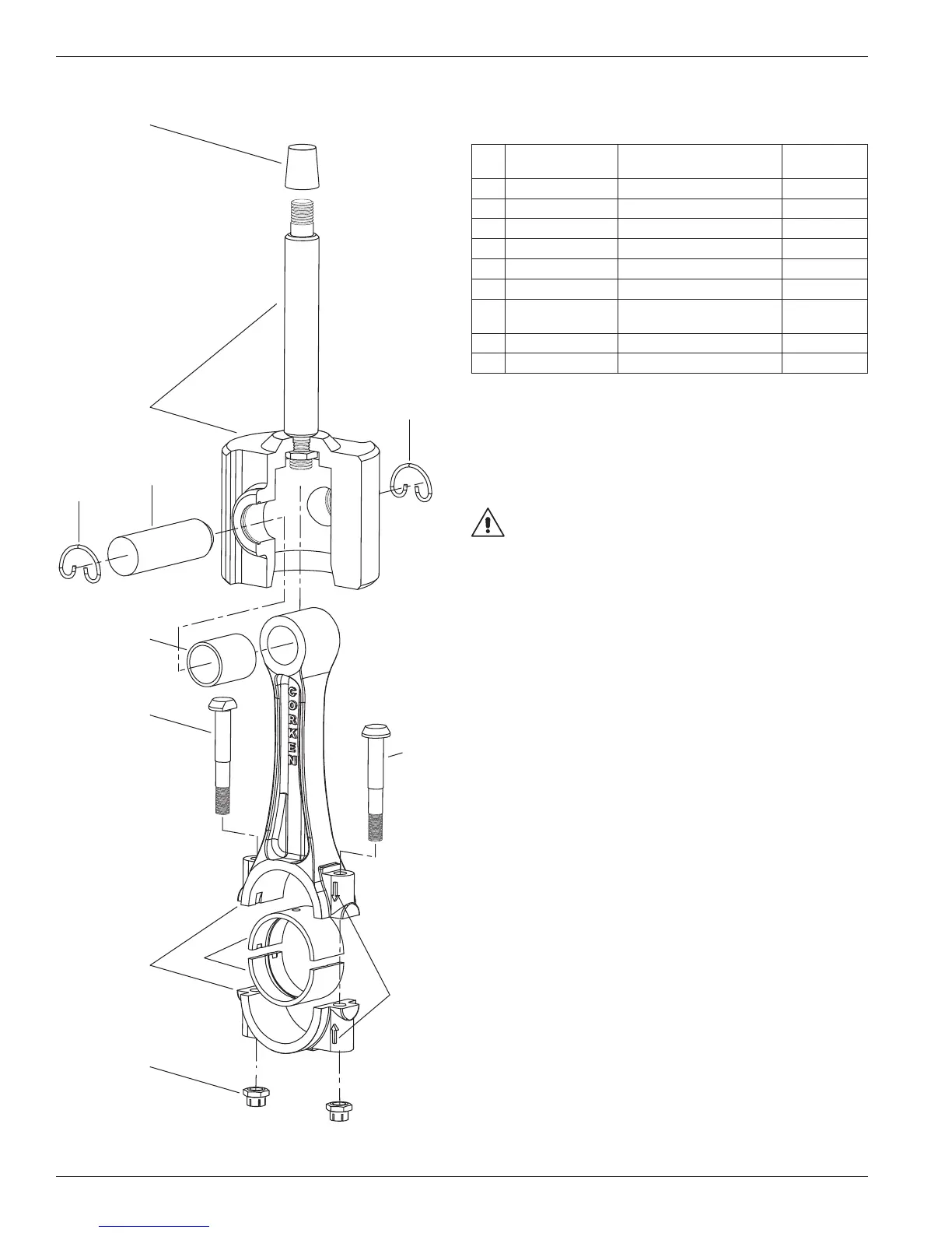
Appendix E—Parts Details for 491 and F491 Connecting Rod Assembly
Connecting Rod—Bill of Materials
Ref
No.
Part No. Description
Qty. per
Compressor
1. 1384-X Crosshead assembly 2
2. 1498 Retainer ring 4
3. 1496 Wrist pin 2
4. 1495-X
a, b
Wrist pin bushing 2
5. 1492
b
Bolt 4
6. 1490-X Connecting rod assembly 2
7. 1491
b
Connecting rod bearing
(pair)
2
8. 1493
b, c
Nut 4
9. 4005 Packing installation cone 1
a
After the wrist pin bushing has been pressed into the connecting rod, it
must be honed to .8759/.8756. A hydraulic press and honing machine are
recommended for this step.
b
Included with connecting rod assembly.
c
Torque connecting rod nut to 30 ft. lbs.
Never attempt to separate the piston rod and crosshead. When repair
becomes necessary, the entire crosshead assembly must be replaced.
WARNING
CAUTION: Always relieve pressure in the unit before attempting
any repairs.
78