1
2
5
4
3
5
7
8
6
Note
alignment
marks
8
2
9
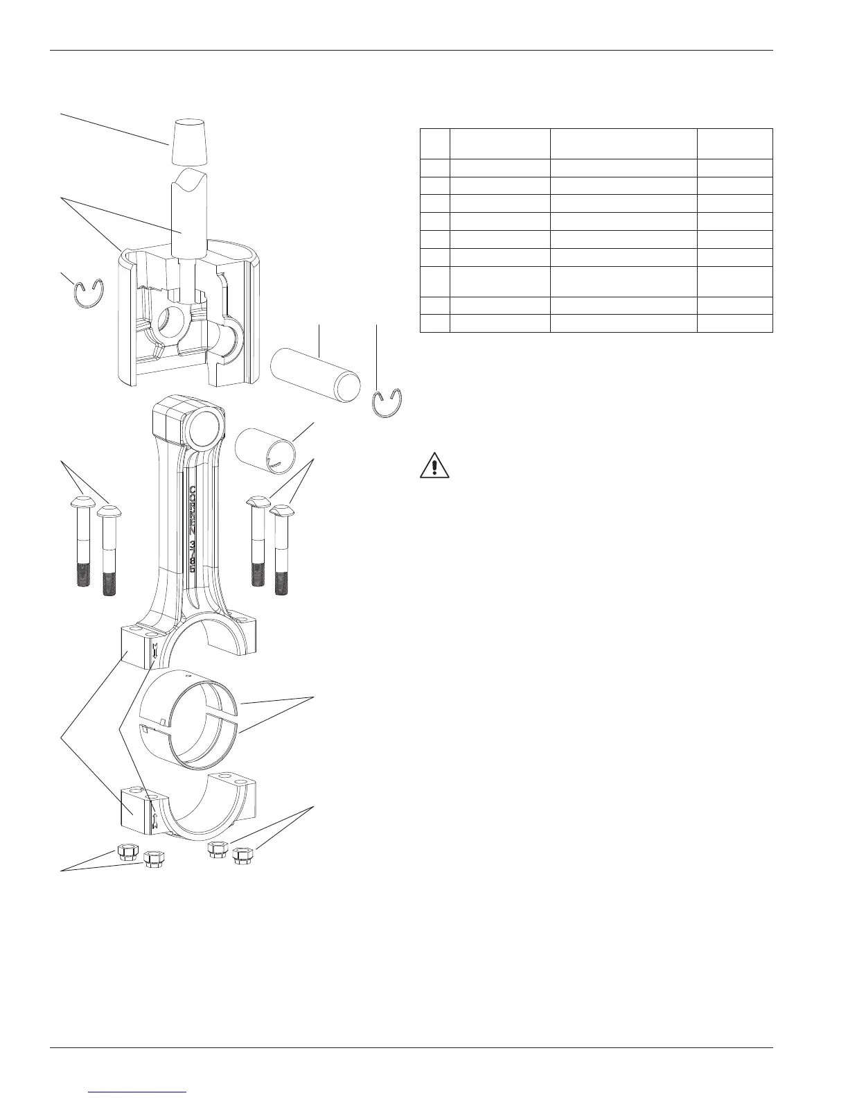
Appendix E—Parts Details for D891 and FD891 Connecting Rod Assembly
Connecting Rod—Bill of Materials
Ref
No.
Part No. Description
Qty. per
Compressor
1. 3544-X3 Crosshead assembly 2
2. 3590 Retainer ring 4
3. 3540 Wrist pin 2
4. 3541-X
a, c
Wrist pin bushing 2
5. 1726
a
Bolt 8
6. 3785-X1
a
Connecting rod assembly 2
7. 3542
a
Connecting rod bearing
(pair)
2
8. 1727
a, b
Nut 8
9. 3905 Packing installation cone 1
a
Included with connecting rod assembly
b
Torque connecting rod nut to 40 ft. lbs.
c
After the wrist pin bushing has been pressed into the connecting rod, it
must be honed to 1.1263/1.1259. A hydraulic press and honing machine are
recommended for this step.
Never attempt to separate the piston rod and crosshead. When repair
becomes necessary, the entire crosshead assembly must be replaced.
WARNING
CAUTION: Always relieve pressure in the unit before attempting
any repairs.
94