92
PhaseLose Voltage
Unbalance
The trip voltage of
Phase-PE
The recovery voltage
of Phase-PE
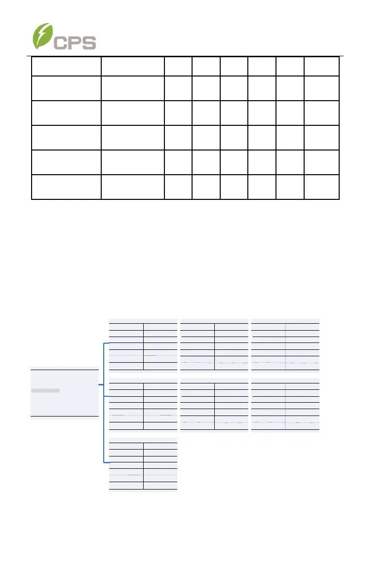
6.2.4 LVRT/HVRT Parameters
LVRT/HVRT” is used to set the LVRT and HVRT parameters. Move the
cursor to this item and press the ENT key to set the parameters. There are
7 pages of LVRT/HVRT parameter settings. These can be changed in the
menu tree or by the LVRT (Figure 6-11) and HVRT (Figure 6-12) graphs.
LVRTTime1(s)
LVRTVol1
P1/7
1.20
0.00%
0.00
0.00%
LVRTVol2
45.00%
1.20
P2/7
10.50
65.00%
10.50
45.00%
65.00%
20.50
LVRTTime2(s)
LVRTTime3(s)
LVRTVol3
LVRTVol4
LVRTTime4(s)
LVRTVol5
LVRTTime5(s)
LVRTTime6(s)
LVRTVol6
P3/7
20.50
83.00%
20.50
83.00%
LVRTTime7(s)
LVRTTime8(s)
LVRTVol7
LVRTVol8
HVRTTime1(s)
HVRTVol1
P4/7
0.80
125.00%
0.00
125.00%
HVRTVol2
124.00%
0.80
P5/7
12.50
115.00%
12.50
124.00%
115.00%
12.50
HVRTTime2(s)
HVRTTime3(s)
HVRTVol3
HVRTVol4
HVRTTime4(s)
HVRTVol5
HVRTTime5(s)
HVRTTime6(s)
HVRTVol6
P6/7
12.50
115.00%
12.50
115.00%
HVRTTime7(s)
HVRTTime8(s)
HVRTVol7
HVRTVol8
LVRT and HVRT Control
LVRTTripVolt
LVRTModeSetting
P7/7
200.0%
150.0%
80.0%
0
LVRTPstReactiveI
0
110.0%
HVRTTripVolt
HVRTModeSetting
LVRTNegReactiveI
LVRT/HVRT Setup
Setting
P1/2
System Parameters
Protection Parameters
Power Derating Setup
Reactive Power Derating Setup
ARC Parameters
Control Command
HVRT Curve
LVRT Curve
HVRT CurveHVRT Curve
LVRT Curve LVRT Curve
Figure 6-10 L/HRVT Parameter Settings