CABRIOLE’
CRAMARO TS S.r.l. – 37044 COLOGNA V.TA (VR) - VIA QUARI DESTRA, 71/G TEL. +39 0442/411688 / FAX + 39 0442/411690
E-MAIL info@cramaro.com WEBSITE: http://www.cramaro.com - Manual n° MCA016-EN-ED00 – date 15/01/15
page 40
FUSE
24 V dc
MOTOR
M
MOTOR
M+
M-
MOTOR
BATTERY
B+
BATTERY
B-
-
+
+
M+
B+B-
M-
FIG 60
FUSE
24 V dc
MOTOR
M
MOTOR
M+
M-
MOTOR
BATTERY
B+
BATTERY
B-
-
+
+
M+
B+B-
M-
FIG 61
FUSE
24 V dc
IC
MOTOR
M+
M-
MOTOR
BATTERY
B+
BATTERY
B-
2 x 2 mm
2
5
4
3
2
1
F
1/2
E
50
40
3
0
2
0
1
0
9
0
8
0
7
0
60
MOTOR
M
2 x 2 mm
2
-
+
M
CC
B+B-
M
CC
+
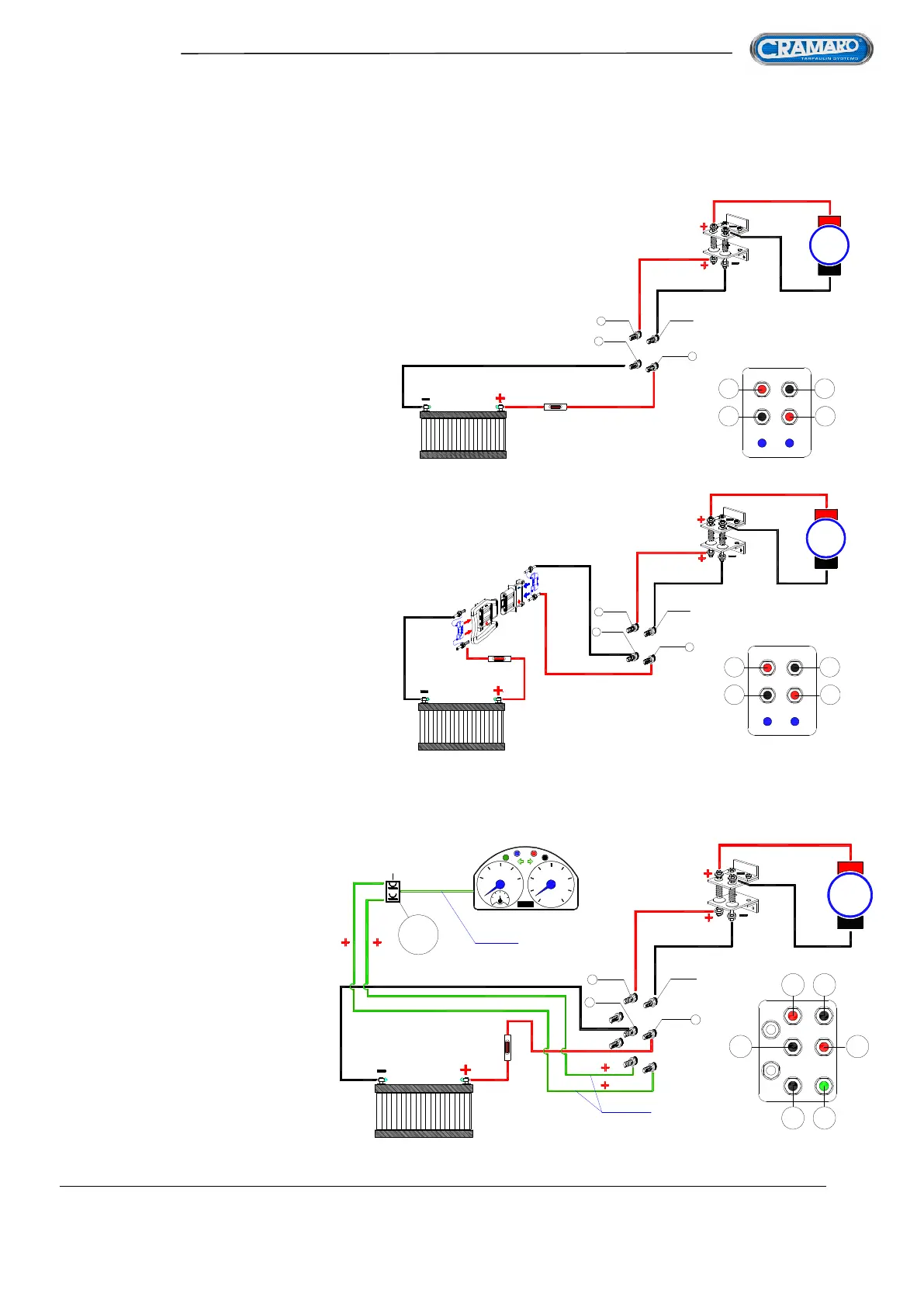
FIG 62
The diagrams to connect the electrical motorisation with the control unit and the vehicle battery can all
basically be traced back to the examples shown below.
STD CONNECTION
FOR TRACTOR
STD CONNECTION
FOR SEMI-TRAILER
CONTROL CONNECTION
IN CAB FOR TRACTOR
IC = switch in cab,
normally open and with positive
connected to power supply
(for example, on the dashboard)