18
Installation
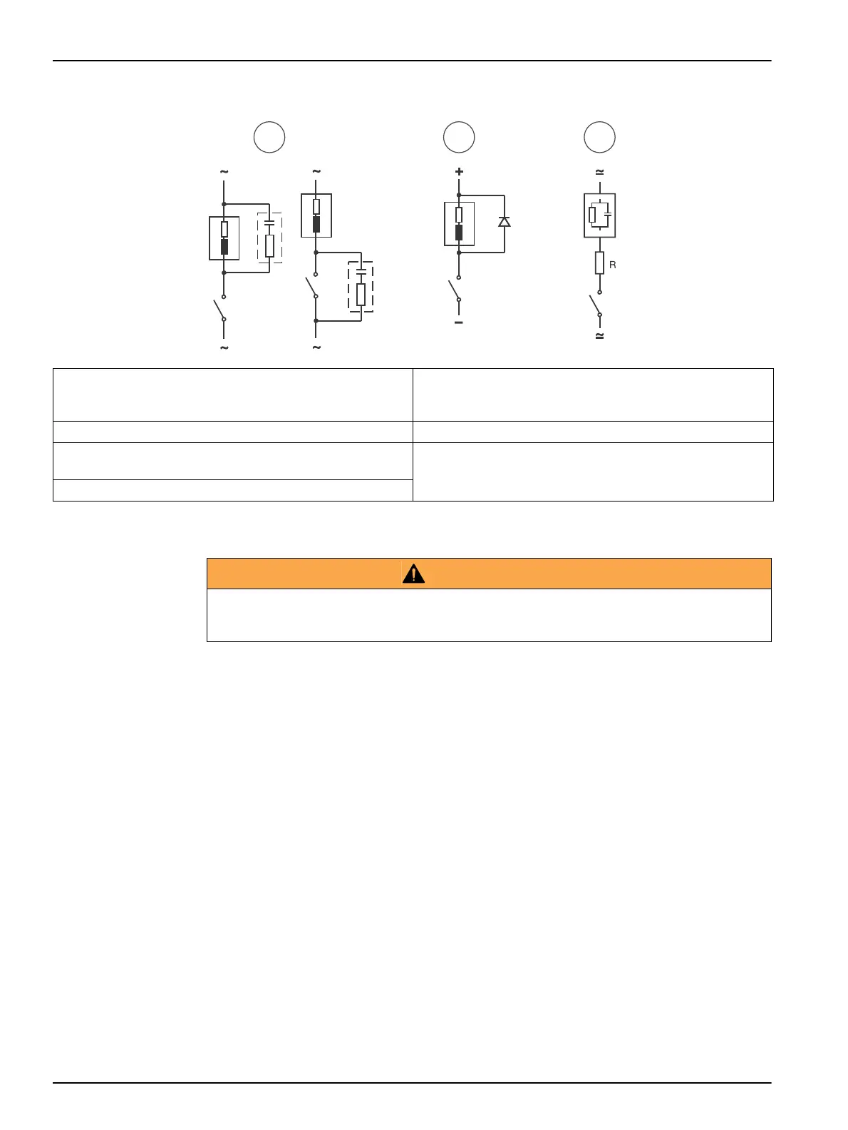
Figure 7 Typical protective wirings
3.5 Installation verification
Important notes:
• During the installation checking the limit relays and alarm relay stay deactivated.
• When a GSM sending is configured, it can be verified as well.
• The optional outputs, 485 and PROFIBUS, can be checked from this option too.
• The External Hold can be checked too.
1. From the measurement display press ESC.
2. Introduce the code 100 and accept with OK.
3. Go to SYSTEM and then CHECK INSTALLATION
4. Select RELAYS or 4-20 MA OUTPUTS to verify.
• Relays: Pressing OK the selected relay is activated. When the OK key is released the
relay is deactivated. The alarm relay acts in opposite manner.
• 4-20 mA output: Select on display the mA value wanted to be simulated.
1 In AC and inductive load
Typical RC at 230 VCA: Capacitor 0.1 µF/630 V;
Resistor 100
Ohms/1 W
5 Load
2 In DC and inductive load 6 RC (resistance and capacitors)
3 In AC/DC and capacitive load
(R example: 5 Ohms/ 1 W at 24 V/0.4 A)
7 Diode: 1N4007
4 Relay contact
WARNING
Relays or 4-20 mA outputs may be connected to control valves or pumps. Before using the relays
or 4-20 mA test options, be sure that those activations cannot produce any damage to people or
an environmental impact.