Page 5
Line
In
Phone
Out
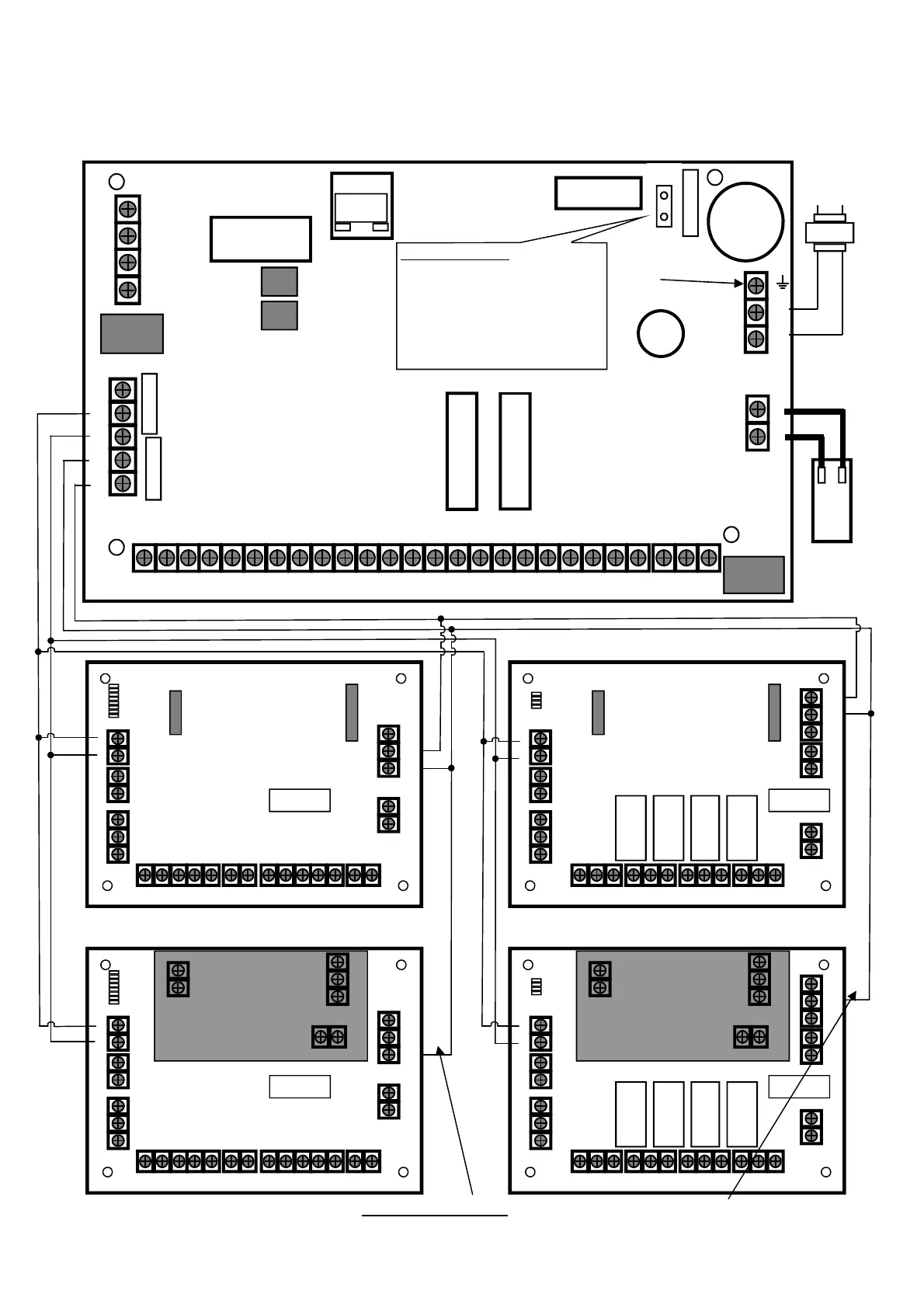
CONNECTION DIAGRAM
LIN DAT CLK NEG POS
RELAY
LINE_OUT
LINE_IN
AC_IN
Outputs
0V 12V 1 2 3 4 0V 12V 1 C 2 3 C 5 4 C 6 7 C 8 TM 0V 12V
NC
EXP 1
RED BLK
Mains
Earth
230V
AC
Input
RUNNER 48/6
V10.00
Bat-
+
_
RST
RESETTING THE PANEL
Power-up the panel with the tamper input in
alarm while shorting out “RST” pins for 5
seconds (you must short out the “RST” pins
before the panel LED starts to flash).
This will Disarm All Armed Areas and allow
access to installer mode by entering <PROG>
<ENTER>.
The Reset feature is disabled if Installer Lock-
out is turned on.
TCP/IP
NO C
SERIAL
EXP 2
17V AC
BATTERY
DIP Switch
- +
13V8IN
TAMP C
0V 12V
OUT
0V 12V
OUT
DAT CLK 0V 12V
OUT
1 2 C 3 4
INPUT
5 6 C 7 8
INPUT
Zone Expander
DAT CLK 0V 12V
OUT
0V 12V
OUT
- +
13V8IN
TAMP C
DIP Switch
Output Expander
NO C NC
RELAY 2
NO C NC
RELAY 3
NO C NC
RELAY 4
NO C NC
RELAY 1
POS
CLK
NEG
DAT
CLK
DAT
CLK
DAT
POS
POS
NEG
NEG
NOTE: If the Plug-in Power supply is fitted DO NOT CONNECT (N/C) the Panel POS to Expander 13.8V IN
If the Wiegand Interface board is used you must follow the same wiring as above.
13.8V
N/C
13.8V
N/C
DIP Switch
- +
13V8IN
TAMP C
0V 12V
OUT
0V 12V
OUT
DAT CLK 0V 12V
OUT
1 2 C 3 4
INPUT
5 6 C 7 8
INPUT
Zone Expander
- +
- +
Plug-in Power supply
12V-24V-AC-AC
0V 12V
OUT
- +
13V8IN
DAT CLK 0V 12V
OUT
TAMP C
DIP Switch
Output Expander
NO C NC
RELAY 2
NO C NC
RELAY 3
NO C NC
RELAY 4
NO C NC
RELAY 1
- +
- +
Plug-in Power supply
12V-24V-AC-AC