Page 7
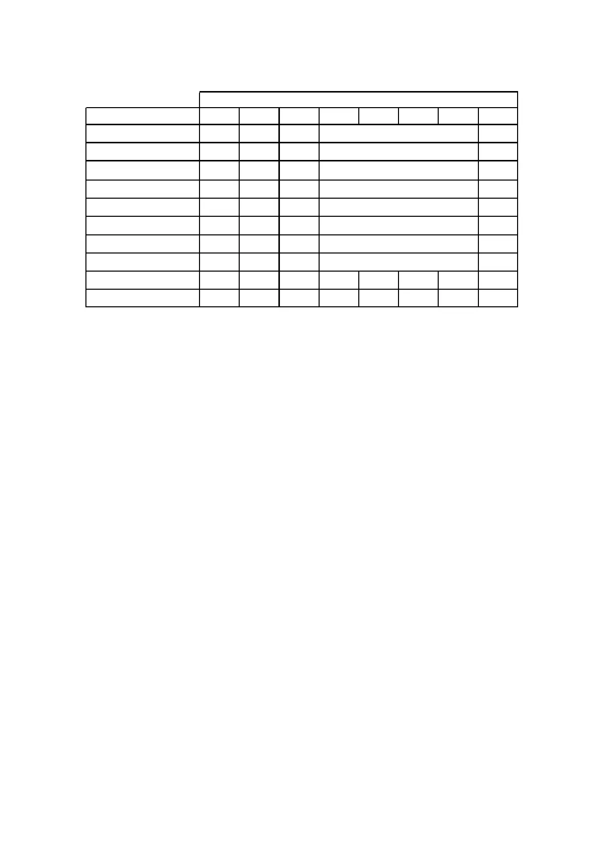
Output Expander DIP Switch settings
DIP switch number 8 disables the on-board tamper input if not required.
DIP Switches 4, 5, 6, & 7 are currently unused.
There is an LED associated with every output. They are labelled OUTPUT 1-4.
LED 1 relates to output 1 through to LED 4 relates to output 4.
At power up the LED’s will cycle in numerical order back and forth until communications is established with the main
control panel. If there is an address clash (eg two output expanders set to the same address number) they will con-
tinue to cycle until the clash is resolved by changing the switches on one of the expanders.
Under normal conditions the LED’s will be off when the output is off. When an LED is on that indicates the associated
relay is on.
The output expander can be powered from the main control panel (as shown on the connection diagram on the previ-
ous page) or there is an optional plug in 1A power supply module that can be fitted to the output expander.
When the optional power supply module is fitted the 13.8V (POS) from the panel must not be connected, only the 0V
from the main control panel should be connected to the output expander 0V.
DIP Switch #
Output Expander Number 1 2 3 4 5 6 7 8
O/P EXP # 1
off off off
Follows Outputs 1-4
O/P EXP # 2 ON
off off
Follows Outputs 5-8
O/P EXP # 3
off
ON
off
Follows Outputs 9-12
O/P EXP # 4 ON ON
off
Follows Outputs 13-16
O/P EXP # 5
off off
ON Follows Outputs 17-20
O/P EXP # 6 ON
off
ON Follows Outputs 21-24
O/P EXP # 7
off
ON ON Follows Outputs 25-28
O/P EXP # 8 ON ON ON
On Board Tamper Ignored ON
On Board Tamper Active
off
Follows Outputs 29-32