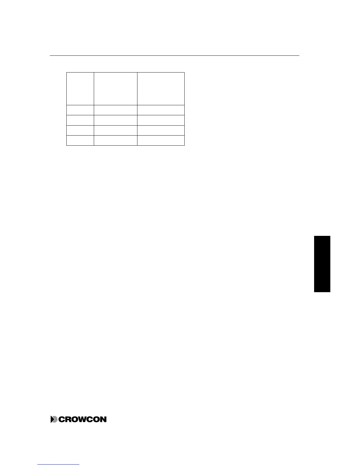
Table 5: Cable characteristics
c.s.a
(mm
2
)
See note
Typical
Resistance per
Km of Cable
(Ohms)
Typical Loop
Resistance per
Km of Cable
(Ohms)
0.5 (20) 39.0 78.0
1.0 (17) 18.1 36.2
1.5 (15) 12.1 24.2
2.5 (13) 8.0 16.0
Note: Approximate c.s.a. in awg given in brackets.
Cable lengths should be calibrated according to the equations defined in the detector instructions sheet
and the cable and Vortex characteristics specified above.
Vortex provides a number of internal and external earth terminals for safety earth and screen
terminations. See Appendix F for further information on earthing.
Vortex has been tested and found to be compliant with EMC regulations using the following cable and
gland configurations:
• SWA cable and SWA glands with electrical termination of the armour to the casing via the gland
• Screened cable with the screen terminated inside the casing via a metal tag attached to the gland,
or terminated at the earth stud.
• Screened cable using an EMC gland where the screen is terminated to the enclosure via the gland
The Vortex standard enclosure contains cable entries with knockout plugs (18 at the top and 18 at the
bottom). These can be fitted with a standard M20 cable gland.
3.7 Circuit Breaker
If the equipment is permanently connected to a mains supply then a circuit breaker must be included in
the installation, in order to comply with the requirements of EN 61010-1 (Low Voltage Directive).
The circuit breaker must be close to Vortex and within easy reach of the operator. It must be marked as
the disconnecting device for the Vortex.
The circuit breaker must comply with the relevant requirements of IEC 947-1 and IEC 947-3. The
protective earth must not be disconnected even when the breaker is activated.