Vortex Manual Operation
Issue 7 December 2009 47
OPERATION
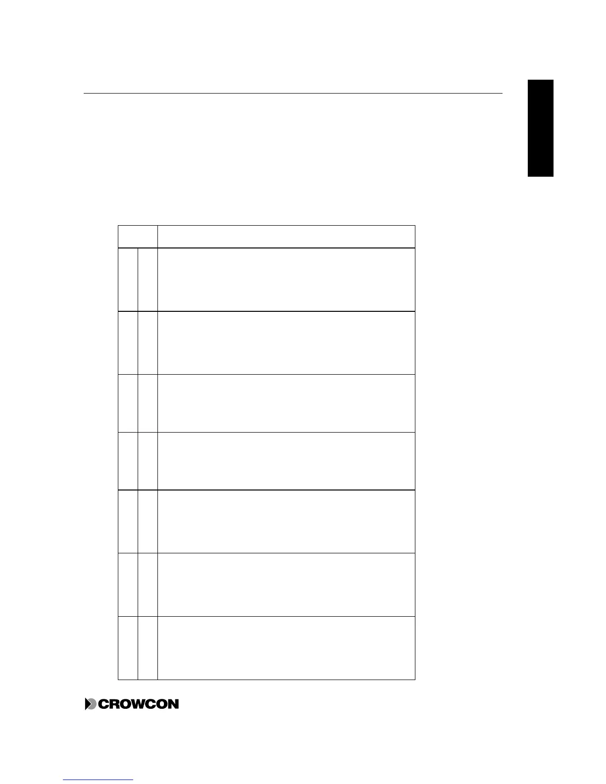
6.4.3 System Faults.
There are several system faults that are indicated by the System Fault LED on the Display Module.
The Fault LEDs on the Node Controller Module indicate what system error has occurred using a
binary code.
Table 19: List of Node Controller Module LED fault codes
● = lit, ○ = unlit
Code Fault description
○
○
○
No fault
○
●
1 Battery fault.
The battery is seriously discharged or disconnected. Reconnect or
replace the battery. If no battery is fitted, ensure link LK1, on the
power monitor module, is made.
●
○
2 FRAM data integrity fault
Node Controller Module problem. Contact Crowcon.
●
●
3 Internal bus fault.
Problem with the Ribbon Cable between the Display Module,
Node Controller and the Power Monitoring Module. Check the
Ribbon Cable is connected and intact. If persists contact Crowcon.
○
○
4 Display access fault.
Check the connection between the Node Controller Module and
the Display Module. If persists contact Crowcon.
○
●
5 Power Monitoring Module access fault.
Check the connection between the Node Controller Module and
the Power Monitoring Module. If persists contact Crowcon.
●
○
6 External bus fault.
Ensure all modules are located on the Bus Rail correctly. If the
fault persists contact Crowcon.