4.5 Relay Output Module
4.5.1 Functions of the Relay Output Module
Optional Relay Output Modules may be fitted to the system and programmed to provide voted channel
and system events. These relays are controlled by the Node Controller Module.
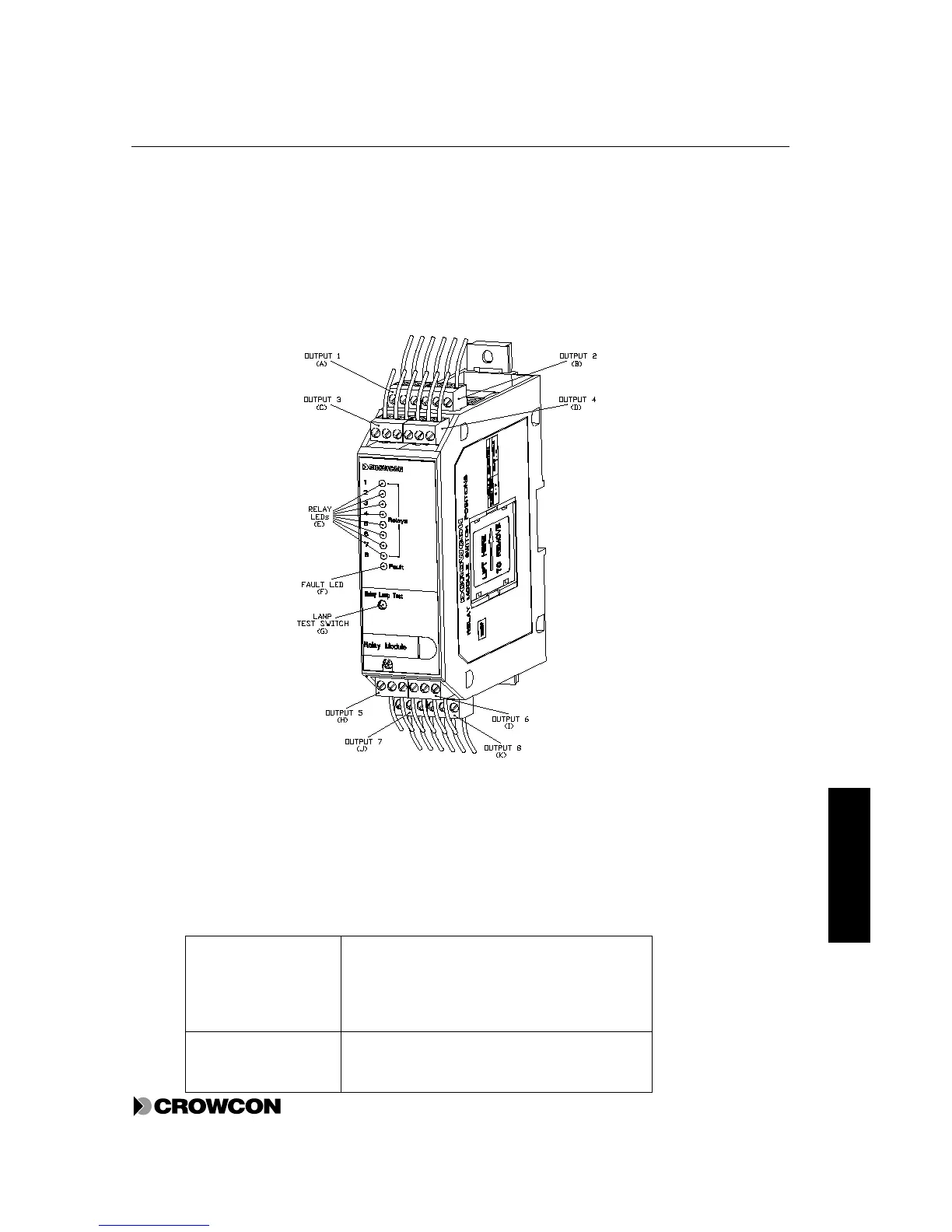
Figure 7: Relay Output Module
Figure 7 gives a general view of a Relay Output Module.
Table 10: Features of the Relay Output Module
Letters refer to the labels in Figure 7.
Relays 8 Single-Pole-Change-Over (SPCO) relays rated
at 6A 250Vac. These relays are configurable
separately for channel, alarm, voting, time delays
and relay type. Configuration is done through the
VortexPC software.
Relay Outputs (A to D
and H to K)
Connection to each relay 1 to 8. Normally open,
normally closed and common connections are
defined in appendix B Figure 19