Detector Type Switch
input 1 to 4 (H, I, J
and K).
Selects the Detector Type.
Position 1 - 3-wire, 4-20mA source detector
Position 2 - 2-wire, 4-20mA
3-wire, 4-20mA sink detector
Position 3 - 2-wire, 0-5V
Position 4 - Fire (Channel 1 of module only)
Each detector channel is configured using VortexPC. Choose the Inputs Configuration option on the
Vortex menu. Select the appropriate channel to view its current configuration. See Table 9.
These properties apply to all channels regardless of their Detector Type (except Enabled, which is not
available for channels set as Not Configured detectors).
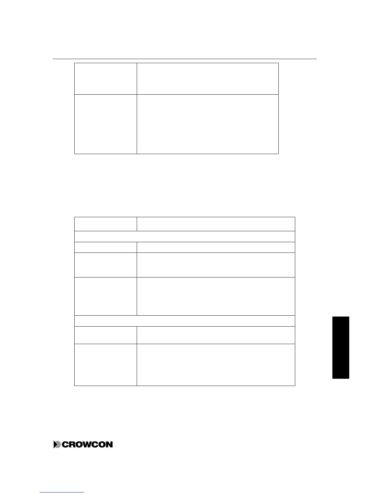
Table 9: Detector channel configurable properties
Property Configuration
Channels
Identity An 8-character string used to identify the channel
Detector Type Gas
Fire (Channel 1 of module only)
Not Configured if channel has no detector
Enabled On/Off. A detector must be enabled and configured to
participate in the system. If there are no participating detectors,
an E002 error is generated. A channel may be removed from the
system using this option even if it is configured, for example, a
faulty detector.
Gas detectors
Units Selects the units for Gas Detectors: %LEL, %VOL, ppm or no
units
Range For %LEL and %VOL the range can be 0 to 1, 2, 2.5, 5, 10, 20,
25, 50 or 100.
For ppm the range can be 0 to 1, 2, 2.5, 5, 10, 20, 25, 50, 100,
200, 250, 500, 1000, 2000, 2500, 5000, 10000. For the 10000
range, the maximum display is 9990.