4.4.2 Configuring the Quad Channel Input Module
The Quad Channel Input Module has switches for Detector Type, Selection and Module Selection, and
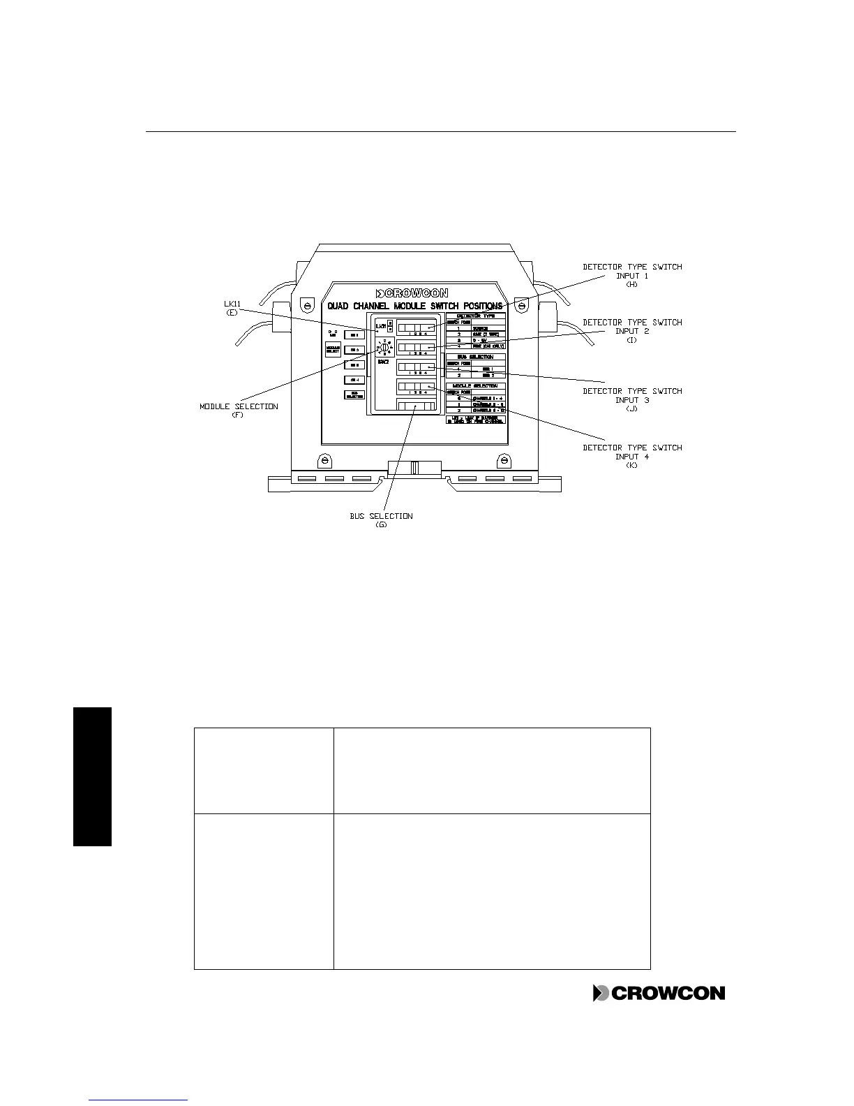
a link LK11. See Figure 6
Figure 6: Switches on Quad Channel Input Module
If the system is supplied with Crowcon detectors, the Quad Channel Input Modules are already
configured. If the system needs configuring, follow the instructions below.
Table 8: Quad Channel Input Module switch settings
Letters refer to labels in Figure 6.
LK 11 (E)
If the first channel of a module is a fire detector
connected to the Vortex system via a Zener Barrier, then
make the link LK11. In all other cases, including when
the fire detectors are connected directly to the panel,
leave this link unmade.
Module Selection
Switch (F)
Determines the channel number for the module. The
physical order of the modules on the Bus Rail is not
important.
Position 0 - This module has channels 1-4
Position 1 - This module has channels 5-8 if two or three
modules are used
Position 2 - This module has channels 9-12 if three
modules are used