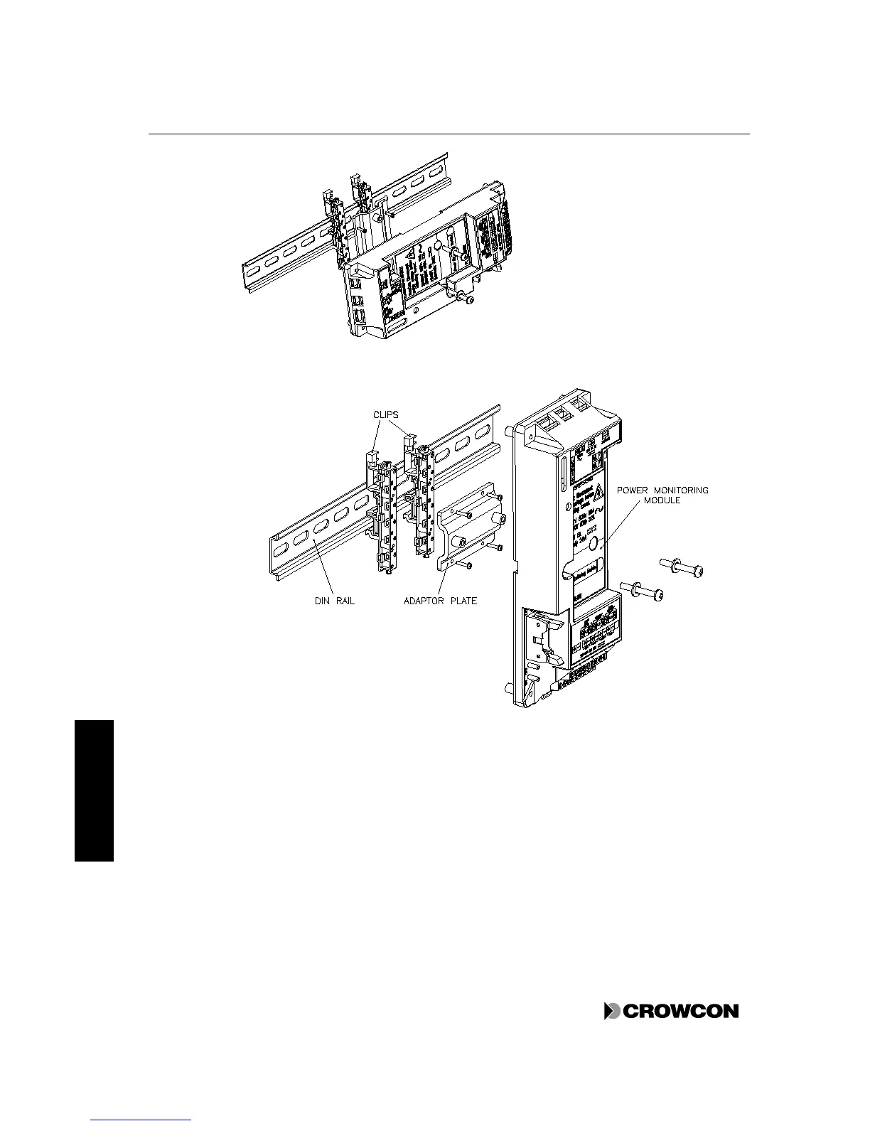
Figure 12: Alternative mountings for the Power Monitoring Module
4.7.4 Backup batteries
The Power Monitoring Module is capable of charging and monitoring two 12V, 2Ah at 0.25A, sealed
lead-acid batteries connected in series to provide 24V dc. If the main ac power supply is lost, the
system automatically switches over to the standby battery operation, this is indicated on the Power
Status LED on the Display Module. If loss of power continues, the battery is disconnected from the
system to prevent it from being over-discharged and permanently damaged.
In the Vortex standard enclosure these batteries are mounted behind the Power Monitoring Module.
There is a 10A in-line fuse between the two batteries behind the Power Monitoring Module. For
instructions on changing these batteries, see section 7.9.