Technical Information Vortex Manual
36 Issue 7 December 2009
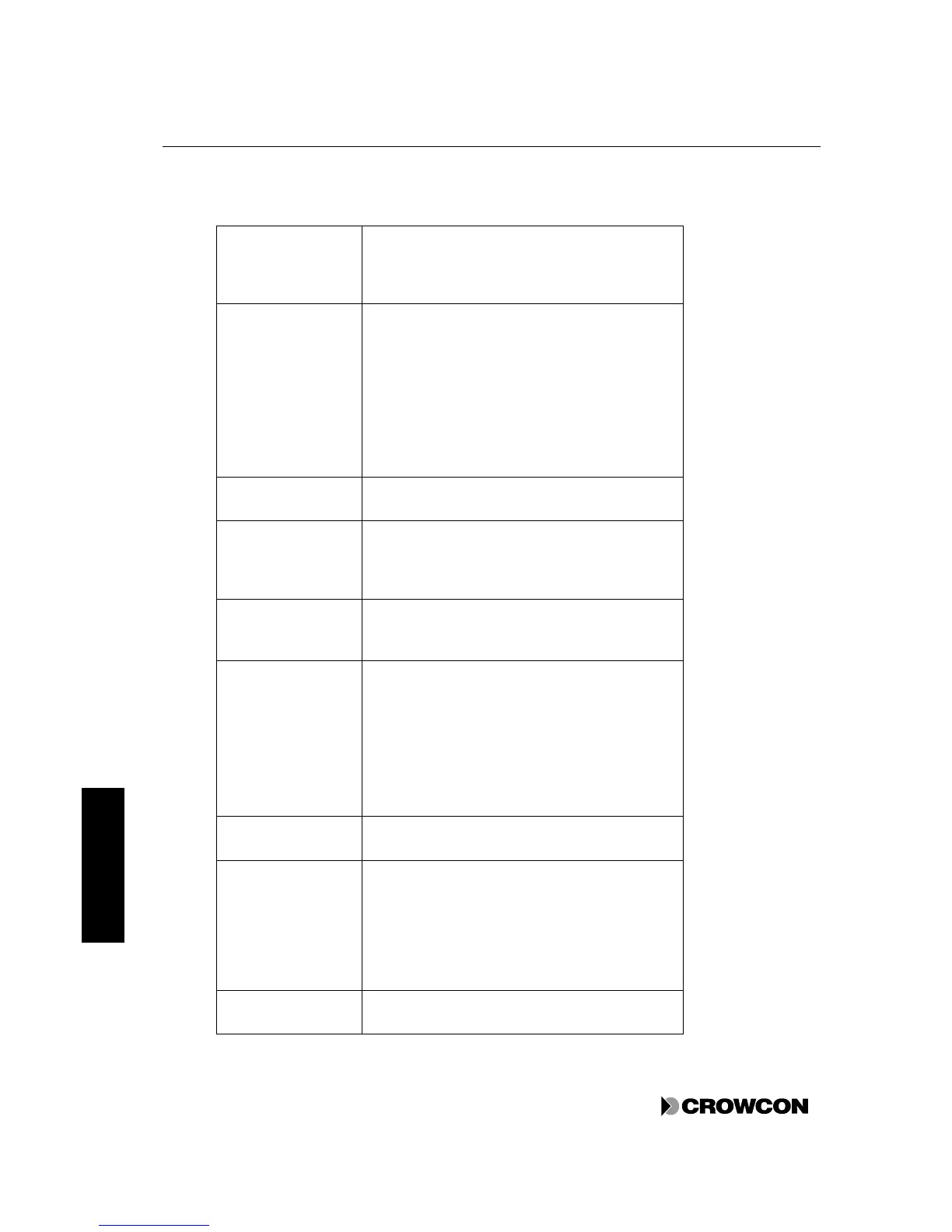
Table 16: Features of the Power Monitoring Module
Letters refer to labels in Figure 11, page 35.
Mains (connector)
(A)
Input from mains supply, when the optional Power
Supply Unit is fitted. This is rated at 29.5V, 150W,
with input at 110-120V or 220 to 230Vac
(switched), 50-60Hz.
If a 24Vdc external power source is specified, then
the Mains Power Supply Unit is not fitted. A 20-
30Vdc supply fused at 5A must be provided. The
Power Monitoring Module includes 24V filtering.
You must ensure that the 24Vdc is suitable for use
with Vortex.
If internal batteries are expected to be charged from
an external DC supply then the supply should have
a minimum voltage of 29.0V
(C)
Connection to backup batteries. See section 4.7.4.
The lower fuse is connected to the batteries (if
fitted) and the upper fuse is connected to the dc
output of the mains power supply and the 24V dc
input (item B).
This indicates that there is DC input to the power
monitor board, either from the mains power supply
unit or from the DC input (item B)
LK1 and LK2 (links)
(F)
LK1 must be fitted if the system does not have
standby batteries fitted. If neither the link nor the
batteries are fitted then a Power Status Fault will
always be present.
If the system is to be powered up without an
external power supply, LK2 can be shorted to
enable the system to power up from fully-charged
batteries.
This connects to the Node Controller Module
(section 4.2) and the Display Module (if fitted).
When Vortex is supplied in the standard enclosure,
it is supplied with the enclosure isolated from 0V
and the earth link fitted to TP2. This link is required
for systems where the 0V is isolated from the
enclosure. If the system requires the 0V to be
connected to the enclosure, move the link wire to
TP1. See Appendix F for further details of earthing.
This is the output from the power monitor module
for connecting to the bus assembly see section 4.3