Maintenance Vortex Manual
52 Issue 7 December 2009
MAINTENANCE
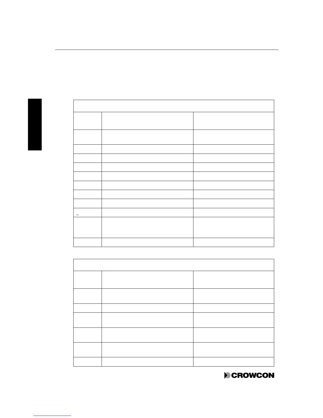
4. Press the Channel Test button repeatedly to display the levels in the order shown in Table 20. If
the channel is not inhibited, the relays are tripped as the sequence passes through them. This can
be used to test that the relays and their devices are working correctly.
Note that the individual alarms are operated independently, depending on their thresholds and
whether they are set as rising or falling, so more than one alarm may be present at one time.
Table 20: Channel test display sequences
Gas detector channel
Channel
display
State Reading display
GL Starting point. Alarm status according to
input signal level.
Gas Level
A1 Alarm level 1 active Alarm Level 1
A2 Alarm level 2 active Alarm Level 2
A3 Alarm level 3 active Alarm Level 3
FS All rising alarms active Full Scale
A3 Alarm level 1 active Alarm Level 3
A2 Alarm level 2 active Alarm Level 2
A1 Alarm level 3 active Alarm Level 1
0 All falling alarms active Zero
F (Fault) Fault LED is on solidly. A zero level is
forced so that falling alarms are active.
This test does not trigger the fault relay.
E (possibly with a fault number)
GL Back to starting point Gas Level
Fire detector channel
Channel
display
State Reading display
FL Starting point. Alarm status according to
input signal level.
Fire Level
OC No alarms active. Fault active. Open Circuit
AL Alarm levels 1,2 and 3 active. No fault
active.
Alarm Level
SC Alarm levels 1, 2 and 3 active and fault
active.
Short Circuit
FS Alarm levels 1, 2 and 3 active and fault
active.
Full Scale
0 No alarms active. Fault active. Zero