Chapter 7: Gripper Installation 59
99-04-23
Pneumatic Gripper
The pneumatic gripper is supplied with two
1
/
16
inch [1.6 mm] barbed fittings.
Caution! Design your pneumatic tooling so that, during a power failure, safe gripping
is maintained.
To connect the pneumatic gripper:
1. Screw a barbed fitting into each of the two ports of the pneumatic connector on
the right side of the arm.
2. At the arm end of the gripper’s air hose, separate the two air hoses for
approximately 1 in. [25 mm] of length.
3. Push one hose onto one barbed fitting and the other hose onto the other fitting.
4. Connect the workshop air supply to the
1
/
8
NPT air port at the rear of the robot
base. Use only dry, clean, filtered, non-lubricated air at a maximum of 100 psi
[6.89 kPa] [6.89 Bar].
5. Test the operation of the gripper.
• At the teach pendant, press the GRIP key. Press GRIP CLOSE and press
GRIP OPEN.
• Check that OPEN opens the gripper and CLOSE
closes the gripper.
• If the operation of the gripper is reversed (OPEN closes the gripper and
CLOSE opens the gripper), reverse the connections of the two hoses with
the two barbed fittings.
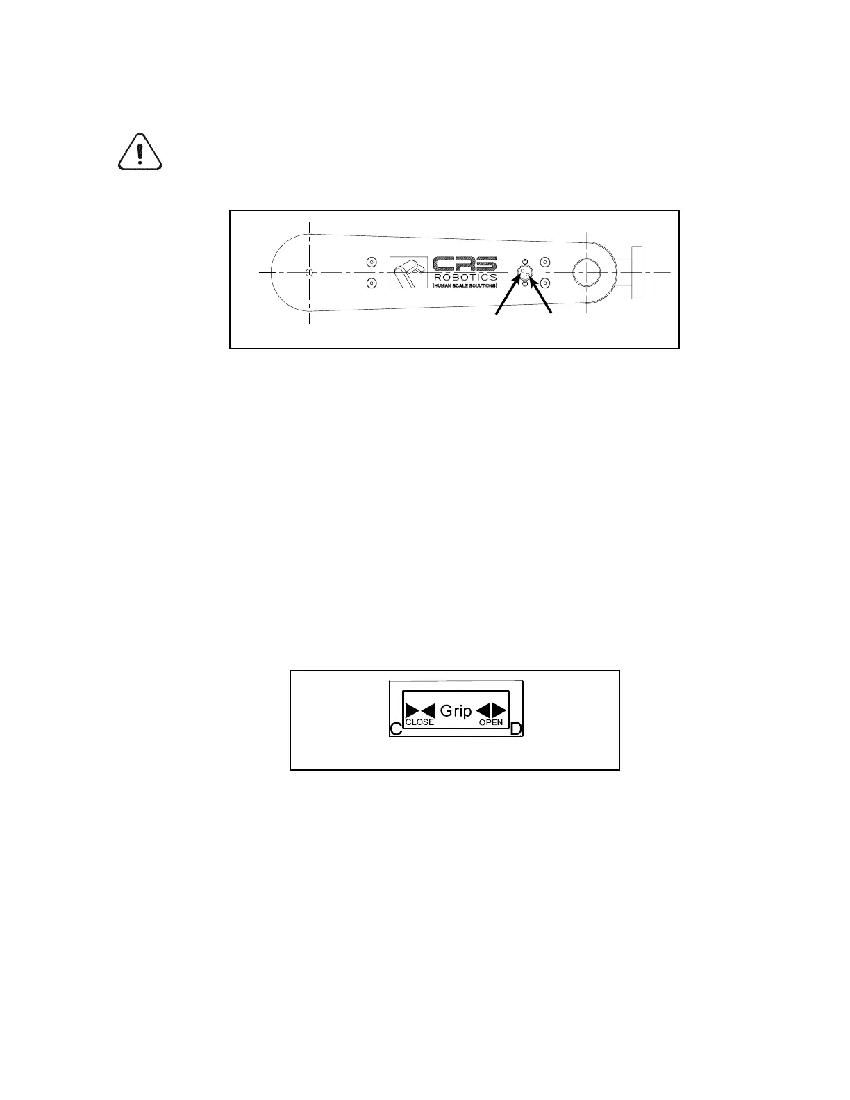
Air Ports
There are two air ports on the side of the arm.
• Pressing the OPEN
key or issuing the open command initiates air flow from the
port closest to the wrist joint.
• Pressing the CLOSE key or issuing the close command initiates air flow from
the port furthest from the wrist joint.
Enabling the Gripper
To enable the gripper:
The two air ports for the pneumatic gripper.
The teach pendant’s gripper close and open keys.