58 A255 Robot Arm User Guide
99-04-23
2) Attach the Gripper
1. Align the tool flange homing pointer anywhere near its homing zone, and
position the gripper on the flange in your preferred position, either vertical or
horizontal.
2. Position the gripper on the robot tool flange. Avoid straining the gripper cable,
connector, hoses, and fittings.
3. From the rear of the robot tool flange, insert and hand-tighten the four #10–24
x
3
/
8
inch socket head cap screws.
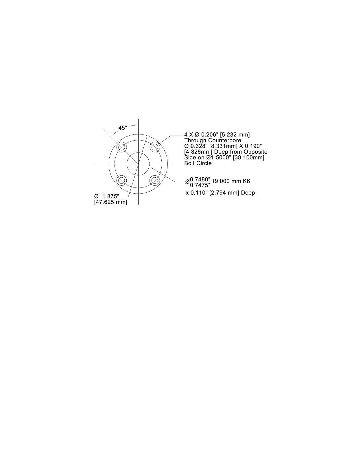
Dimensions of the tool flange for the gripper.
4. Firmly tighten the screws with the hex key.
Connecting the Cable or Hose
The electrical connector is on the left side of the arm.
The pneumatic connector is located on the right side of the arm, approximately 2
½ in. [60 mm] behind the wrist axis.
Servo Gripper
To connect the servo gripper cable:
1. Line up the white dot marker on the gripper cable connector with the white dot
marker on the arm connector.
2. Push the cable connector onto the arm connector until it clicks. The outer
collar is spring loaded.
To disconnect the servo gripper:
1. Pull back the spring loaded outer collar.
2. Pull out the cable connector from the arm connector.
Note: Striking an e-stop does not remove power to the servo gripper. As a safety
feature, motor power to the gripper is maintained so the gripper does not
release its load.
For information on: specifications, testing, operating, maintenance,
troubleshooting, and repair, see the Servo Gripper User Guide.