Chapter 3: Safety Precautions 17
99-04-23
Emergency Stops (E-stops)
An emergency stop (e-stop) button is a large, red, mushroom-shaped button that
removes arm power when struck. It must be manually reset to restore arm power.
The controller e-stop circuit removes arm power. When arm power is removed, fail-
safe brakes engage to prevent the robot from moving due to gravity or inertia.
Brakes are installed on all joints except joint 1.
The e-stop circuit is connected to the:
• E-stop button on the front panel of the controller.
• E-stop button on the front of the teach pendant.
• Live-man switch on the teach pendant.
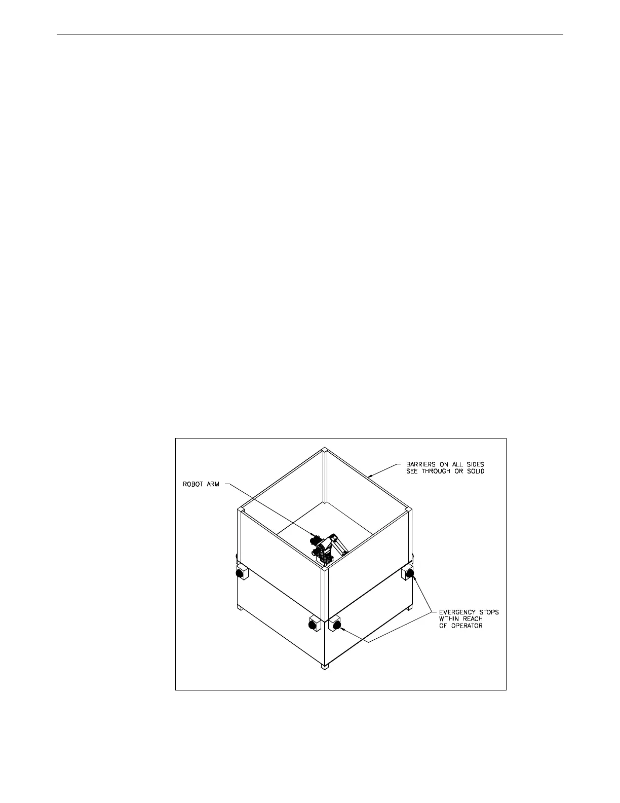
To ensure safety, you can install similar e-stop buttons:
• At or near the robot arm location.
• Within human reach of any approachable side of the robot arm work cell.
Design your workcell so that:
• All e-stop buttons are unobstructed.
• Personnel can reach and activate the e-stop without difficulty.
• All e-stops are outside the total safeguarded space of the robot arm, its
gripper, and any payload. For the dimensions of the workspace of the robot
arm, see Range of Motion on page 4 and Reach on page 6.
If installing other e-stop buttons, see “Installing a Custom E-Stop Circuit” in the
C500C Controller User Guide for connector pin identification and DIP switch
positioning.
Example of barriers and remote e-stops.