Installation
VA 500 Bi-directional English 1.24 Seite 10 von 56
7 Installation
7.1 Pipe/tube requirements
• Correctly sized gaskets
• Correct aligned flanges and gaskets
• Diameter mismatch at the pipe junctions should be avoided but must be less than 1mm. For
further information see ISO 14511
• Ensure clean pipes after installation
• .
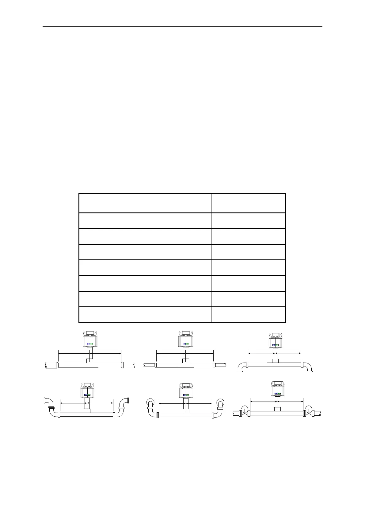
7.2 Inlet / outlet runs
In order to maintain the accuracy stipulated in the data sheets, the sensor must be inserted in the
centre of a straight pip e section with an undisturbed flow progression.
An undisturbed flow progression is achieved if the sections in front of the sensor (inlet) and behind the
sensor (outlet) are sufficiently long, straight and without any obstructions such as edges, seams,
curves etc.
Therefore, it is necessary to ensure the recommended inlet and outlet runs.
Table Inlet / Outlet runs
The values represent the min. lengths. In case the min. inlet / outlet runs could not be ensured, it must
be expected to get increased or significant deviations of the measurement values.