Electrical wiring
VA 500 Bi-directional English 1.24 Seite 23 von 56
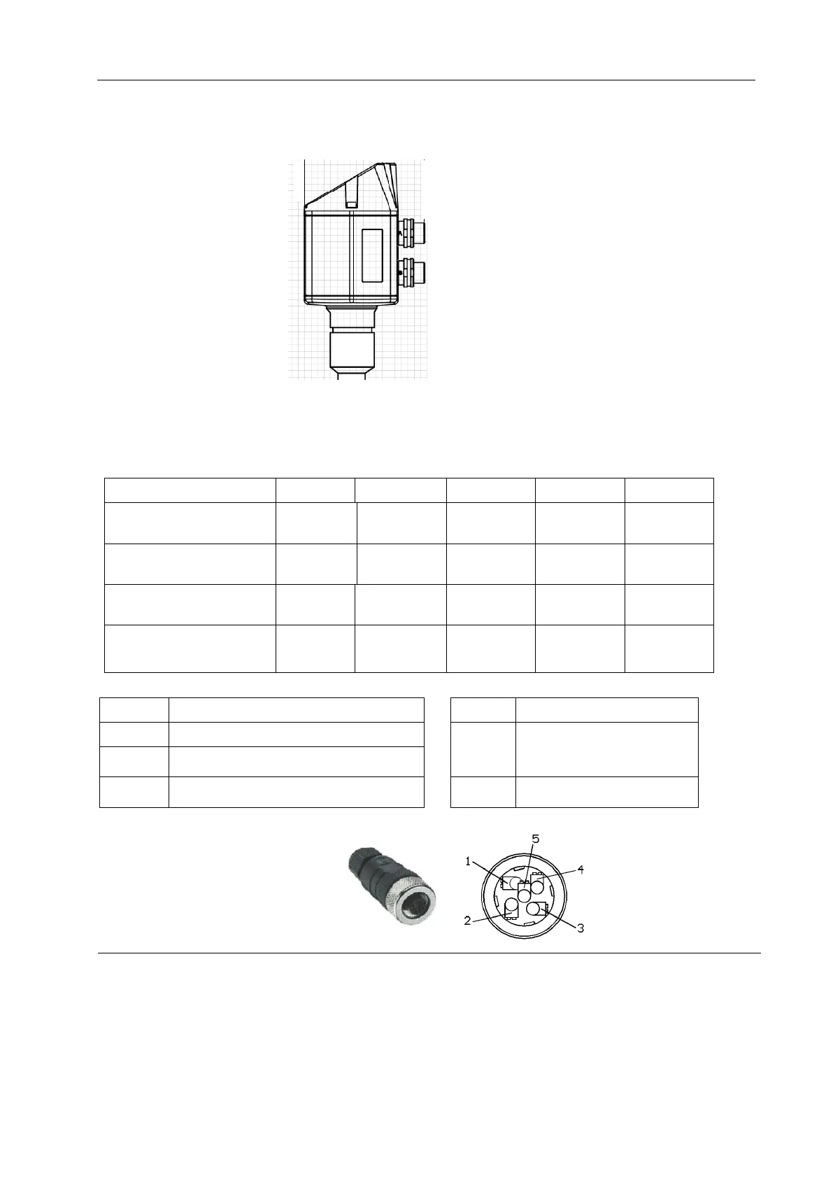
10 Electrical wiring
10.1 Pining for Modbus RTU, 4..20mA, Pulse or MBus
Attention: Not required connections NC must not be connected to a voltage and/or to
protection earth. Cut and insulate cables.
Connector plug B
Pulse output (standard)
Pulse (Ch2)
galv. isolated
Pulse (Ch2)
gavl. isolated
Pulse (Ch1)
galv. isolated
Pulse (Ch1)
gavl. isolated
Connector plug B
Option MBus
Colours pulse cables
0553 0106 (5 m)
0553.0107 (10 m)
Negative supply voltage 0 V
Positive supply voltage 18...36 VDC smoothed
Must not be connected to a voltage
and/or to protection earth. Please
cut and isolate cables.
Current signal 4...20 mA – selected measured
signal
Modbus RTU A / Modbus RTU (+)
Modbus RTU B / Modbus RTU (-)
MBus (reverse polarity protected)
If no connection cable/ pulse
cable is ordered the sensor will
be supplied with a M12
connector plug. The user can
connect the supply and signal
cables as indicated in the
connection diagram.
.
M12 Connector plug
View from back side
(terminal side)
Connector plug A
Connector plug B