Table of Content
VA 500 Bi-directional English 1.24 Seite 3 von 56
II. Table of content
I. Foreword ....................................................................................................................... 2
II. Table of content ......................................................................................................... 3
1 Intended use .................................................................................................................. 5
2 Instruments description ............................................................................................... 5
3 Safety instructions ........................................................................................................ 6
3.1 Warning and information symbols used in these instructions ......................................... 6
3.2 Warnings ................................................................................................................................. 6
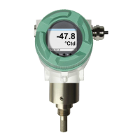
4 VA 500 with Display ...................................................................................................... 8
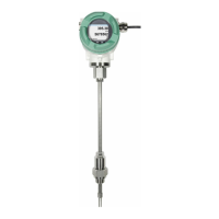
5 VA 500 without Display ................................................................................................. 8
6 Technical data ............................................................................................................... 9
7 Installation ....................................................................................................................10
7.1 Pipe/tube requirements ....................................................................................................... 10
7.2 Inlet / outlet runs .................................................................................................................. 10
7.3 Installation VA 500 ............................................................................................................... 11
7.3.1 ½“ welded nipple with ball valve ½“ ................................................................................. 11
7.3.2 Spot drilling collar with ball valve ..................................................................................... 11
7.4 Installation of the Sensor .................................................................................................... 12
7.4.1 Mounting VA 500 onto the ball valve ............................................................................... 12
8 Measuring ranges ........................................................................................................13
8.1 ................................................................................ 14
8.2 ................................................................................... 16
8.3 ................................................................................. 18
8.4 ................................................................................ 20
9 Dimension ....................................................................................................................22
10 Electrical wiring ........................................................................................................23
10.1 Pining for Modbus RTU, 4..20mA, Pulse or MBus ............................................................ 23
10.2 Connection diagrams .......................................................................................................... 24
10.2.1 Modbus ............................................................................................................................ 24
10.2.2 Analogue output (4-20mA, Pulse).................................................................................... 24
10.2.3 MBus ................................................................................................................................ 24
10.2.4 Ethernet (optional PoE) ................................................................................................... 25