Remark: If the sensor is placed at the end of the Modbus system a termination is required. The sensors have
an internal switchable termination, therefore the 6 fastening screws from the lid are to be released
and set the internal DIP Switch to “On”. It must be ensured that the connection plugs are still plugged
and the gasket is installed correctly.
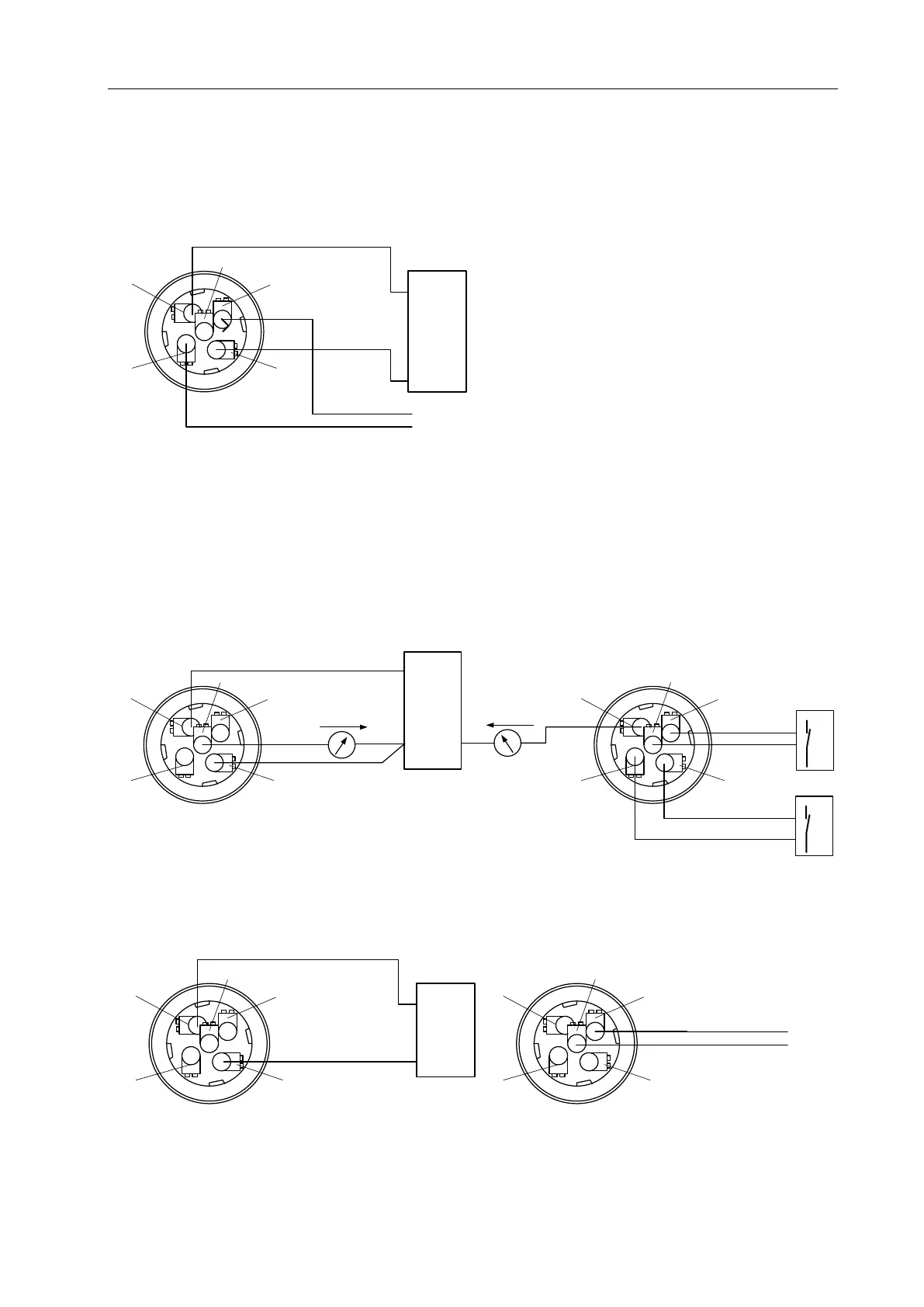
Alternatively, a 120R resistor can be installed in the plug between pin 2 and pin 4.
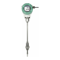
10.2.2 Analogue output (4-20mA, Pulse)
Connector plug A (M12 A-coding) Connector plug B (M12 A-coding)