CVT Drive and brake system
84
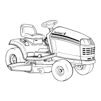
6c. Slip the brake rotor off of the brake shaft
(splined end of bevel gear shaft).
See Figure 6.90.
6d. Inspect the brake shaft and inner brake
pad.
NOTE: The inner pad is epoxied in-place, but
may be pried-out for replacement.
6e. Disassemble and inspect the brake yoke.
See Figure 6.91.
7. Remove the 13 remaining perimeter screws that
hold the upper transaxle housing to the lower
transaxle housing using a 3/8” wrench.
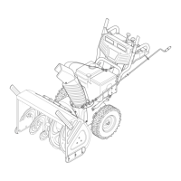
8. Separate the two housings. See Figure 6.92.
NOTE: The axle shafts will generally be of differ-
ent lengths. Mark, or note the orientation of the
differential and axle assembly to the transaxle
housing before removing it.
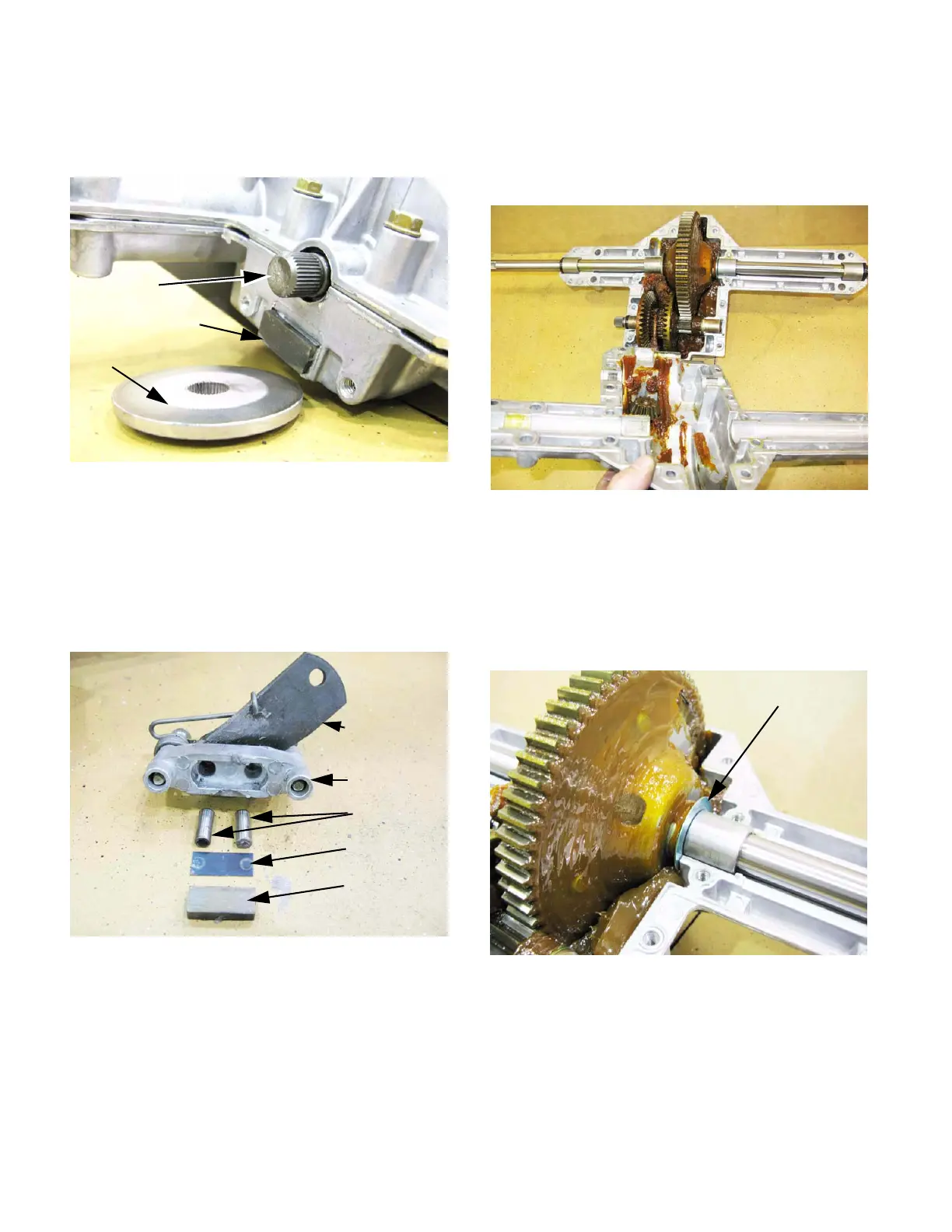
9. Lift the axle and differential housing out of the
transaxle. See Figure 6.93.
10. Note the positions of the shim washers.
Figure 6.90
Brake rotor
Brake pad (fixed)
Brake shaft
Figure 6.91
Brake arm
Brake yoke
Brake pins
Backing plate
Brake pad
Figure 6.92
Lower housing
Upper housing
Figure 6.93
Shims
 Loading...