User Guide DDOC0099-000-AH
DTS1 CSfC ix List of Figures
List of Figures
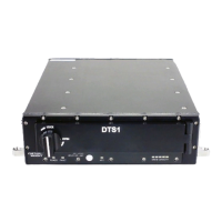
Figure 2.1 DTS1................................................................................................................................................ 2 - 1
Figure 2.2 DTS1 Chassis / Components .......................................................................................................... 2 - 2
Figure 2.3 DTS1 Rear Panel / Battery Access Cover and Rear Connectors.................................................... 2 - 3
Figure 2.4 DTS1 Processor Carrier PCB Programming Connector / Write-Enable Switch .............................. 2 - 3
Figure 2.5 DTS1 With RMC Module ................................................................................................................. 2 - 3
Figure 2.6 Hardware Encryption Layer Account Creation................................................................................. 2 - 5
Figure 2.7 Hardware Encryption Layer Account Login ..................................................................................... 2 - 6
Figure 3.1 DTS1 Controls / Indicators............................................................................................................... 3 - 1
Figure 3.2 Remaining Disk Capacity Indicators ................................................................................................ 3 - 2
Figure 3.3 DTS1 Write-Enable Switch .............................................................................................................. 3 - 2
Figure 3.4 RMC Module Controls / Indicators................................................................................................... 3 - 3
Figure 4.1 DTS1 Chassis Anti-Tamper Label Locations................................................................................... 4 - 1
Figure 4.2 RMC Module Anti-Tamper Label Location....................................................................................... 4 - 2
Figure 4.3 DTS1 Chassis Mounting .................................................................................................................. 4 - 2
Figure 4.4 DTS1 Required Door Clearance...................................................................................................... 4 - 3
Figure 4.5 DTS1 Rear Panel Connectors ......................................................................................................... 4 - 3
Figure 4.6 Power Lab Cable ............................................................................................................................. 4 - 3
Figure 4.7 Utility Lab Cable............................................................................................................................... 4 - 4
Figure 4.8 Ethernet Lab Cable.......................................................................................................................... 4 - 4
Figure 4.9 DTS1 Ground Connection ............................................................................................................... 4 - 5
Figure 5.1 Key Storage Diagram ...................................................................................................................... 5 - 6
Figure 6.1 Initialization Quick Start Process Flow............................................................................................. 6 - 2
Figure 6.2 Login Quick Start Process Flow....................................................................................................... 6 - 4
Figure 7.1 DTS1 Test Setup ............................................................................................................................. 7 - 1
Figure 7.2 PuTTY Terminal Emulator (Serial Data) .......................................................................................... 7 - 2
Figure 7.3 PuTTY Terminal Emulator (SSH) .................................................................................................... 7 - 3
Figure 7.4 DTS1 Update Utility ....................................................................................................................... 7 - 19
Figure 11.1 RMC Module Install / Remove ....................................................................................................... 11 - 1
Figure 11.2 RMC Module Controls, Indicators, and Handle ............................................................................. 11 - 2
Figure 11.3 Battery Assembly Replacement..................................................................................................... 11 - 3
Figure 11.4 Battery Access Panel Screws Tightening Sequence..................................................................... 11 - 3
Figure A.1 RMC Module.................................................................................................................................... A - 1
Figure A.2 DTS1 (Panel Mount) ........................................................................................................................ A - 2
Figure A.3 DTS1 (Dzus Mount) ......................................................................................................................... A - 3
Figure B.1 Power Connector J1 ........................................................................................................................ B - 1
Figure B.2 Power Lab Cable Diagram............................................................................................................... B - 1
Figure B.3 Utility Connector J2.......................................................................................................................... B - 3
Figure B.4 Utility Lab Cable Diagram ................................................................................................................ B - 3
Figure B.5 Ethernet Connector J3..................................................................................................................... B - 4
Figure B.6 Ethernet Lab Cable Wiring Diagram................................................................................................ B - 5