User Guide DDOC0099-000-AH
DTS1 CSfC 4 - 4 Installation
© 2020 Curtiss-Wright Defense Solutions Revision 2.0
Connections
• The 4-pin connector (P1) mates to DTS1 J1.
• The red plug connects to 28 VDC.
• The black plug connects to 28 VDC return
• The green plug connects to chassis ground
• The audio jack (if used) connects to a user-designed power disable switch.
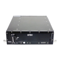
4.4.2 Utility Cable
The Utility Lab Cable (VS-DTS1ETHCAB-J2) (Figure 4.7) is used for initial setup operations
through RS-232 or Ethernet. Refer to paragraph B.2 Utility Connector J2 / Utility Lab Cable for
connector pin signal information.
Connections
• The 19-pin connector (P1) mates to DTS1 J2.
• The RJ-45 plug (P2) connects to a terminal or PC Ethernet port.
• The DB-9 connector (J1) mates to a terminal or PC serial port.
• The audio jack (J2) connects to user-configured switches for zeroization and reboot.
Figure 4.7 Utility Lab Cable
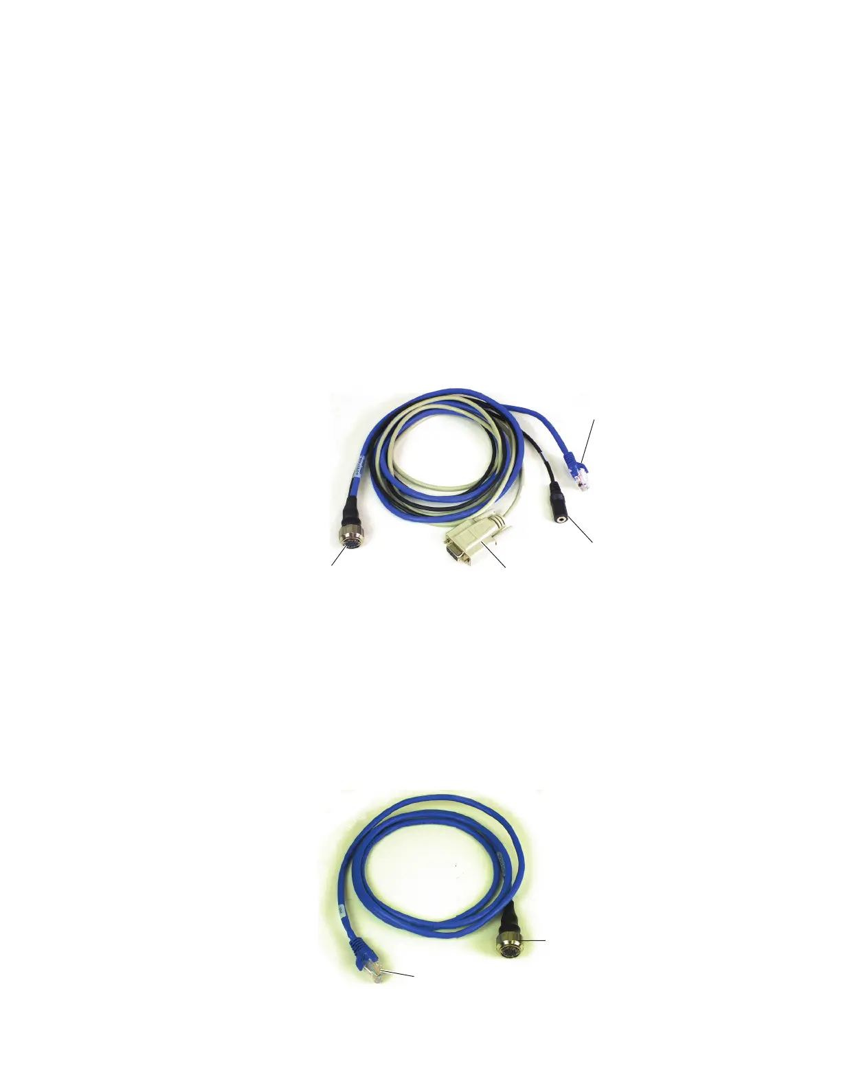
4.4.3 Ethernet Cable
The Ethernet Lab Cable (VS-DTS1ETHCAB-J3) (Figure 4.8) is used to make network connections
to the DTS1. Refer to paragraph B.3 Ethernet Connector J3 / Ethernet Lab Cable for connector
pin signal information.
Connections
• The 19-pin connector (P1) mates to DTS1 J3.
• The RJ-45 plug (P2) connects to the desired network outlet panel, hub, etc.
Figure 4.8 Ethernet Lab Cable
DDOC0099-0011
P1 (19-Pin
Connector)
P2 (RJ45 Plug)
J2 (Audio Jack)
J1 (DB-9
Connector)
DDOC0099-0012
P1 (19-Pin
Connector)
P2 (RJ45 Plug)