User Guide DDOC0099-000-AH
DTS1 CSfC B - 3 Connectors / Cables
© 2020 Curtiss-Wright Defense Solutions Revision 2.0
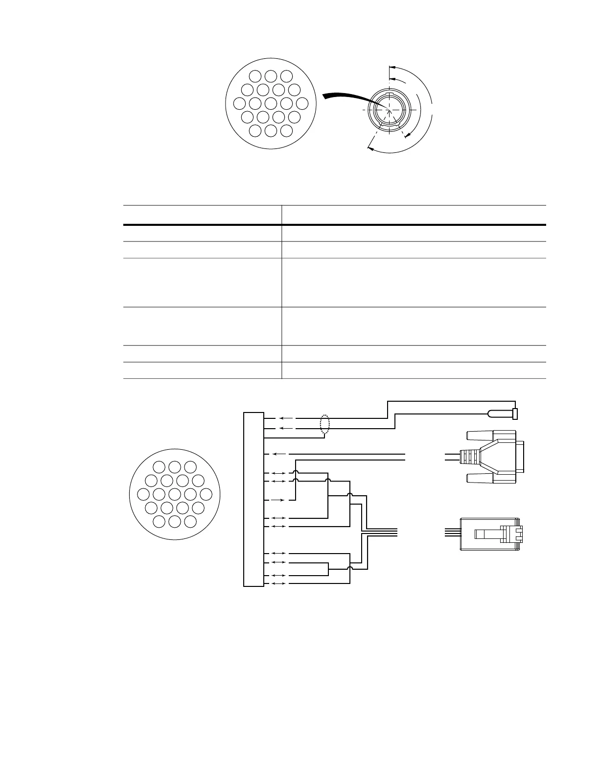
Figure B.3 Utility Connector J2
Figure B.4 Utility Lab Cable Diagram
B.3 Ethernet Connector J3 / Ethernet Lab Cable
Table B.5 provides DTS1 bulkhead J3 connector pin signals. Figure B.5 show the DTS1 bulkhead
J3 connector pinout. Table B.6 shows the DTS1 Ethernet lab cable connection pin signals. Figure
B.6 show the utility lab cable wiring diagram.
Connector Manufacturer Glenair
Connector Reference DesignatorJ3
Connector.........PN 801-023-07M9-19PB
Mating ConnectorPN 801-007-16M9-19SB
Table B.4 Utility Lab Cable (VS-DTS1ETHCAB-J2)
Connector Description Mates With / Signal Name
P1 DTS1 J2
P2 TIA/EIA-568B Modular Plug Gigabit Ethernet TIA/EIA-568B Modular Jack
J1 D-sub DE-9 Female/Socket RS-232
Pin 2: DTS1 transmit
Pin 3: DTS1 receive
Pin 5: GND
J2 3.5mm Audio Jack Tip ZEROIZE – Short to GND to ZEROIZE Crypto Keys. This signal
must be active for a minimum of 5 seconds for the zeroization
process to take affect.
J2 3.5mm Audio Jack Ring RESET – Short to GND to reset DTS1
J2 3.5mm Audio Jack Shield GND
DDOC0099-0040
213
456
891011
19 18
131415
17
12
16
7
150°
210°
213
456
891011
19 18
131415
17
12
16
7
DDOC0099-0037
J1
J2
6
5
4
3
2
1
12
11
10
9
8
7
13
19
18
17
16
15
14
P2
C1
B1
A1
D1
ZEROIZE
RESET
RS-232
ETHERNET
P1