Installing the Gauge
DATA & POWER CONNECTIONS
The Cygnus 1 ROV Gauge can be electrically-connected by one of two methods, depending
on suitability :
Ö Independent-Cable Connection
¾ This is a single cable connecting the Gauge to the surface.
This cable can be supplied, on request, by Cygnus.
¾ This cable is independent of the ROV’s own cabling and has a maximum length of
1000 metres
Ö ROV Local-Termination Connection
¾ In this method the connection from the Gauge is taken to the ROV, and is merged
with the ROV’s own cabling to connect to the surface
¾ It is essential that the Data-connections from the Gauge are maintained throughout
as twisted-pair
¾ Power for the Gauge can be taken from the ROV’s own power supply, if suitable
¾ The Data-output from the Gauge has a maximum capability of 1000 metres :
if the distance from the Gauge to the surface is greater than 1000 metres the Data-
output from the Gauge must be electronically buffered within the ROV.
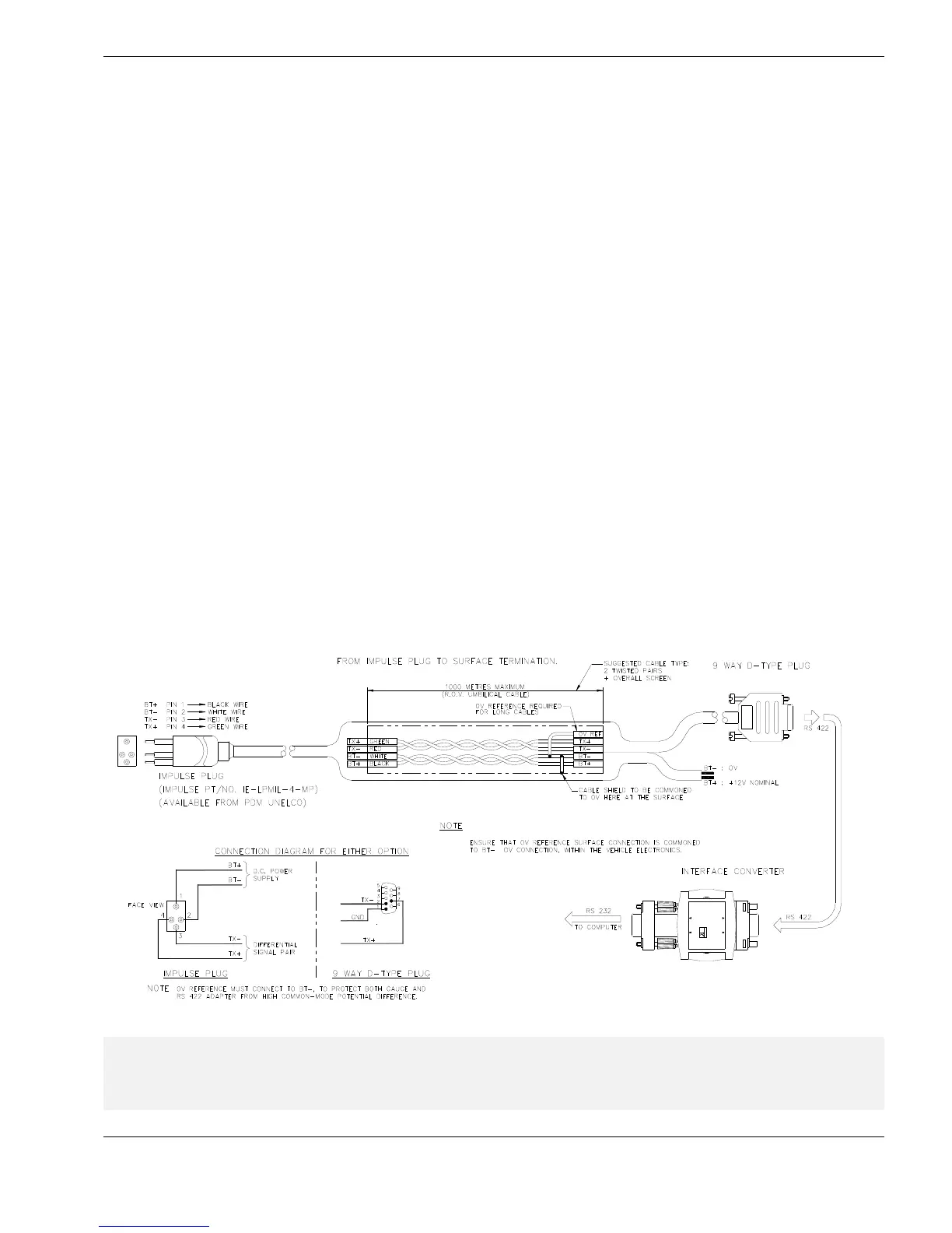
Independent Cable Connection
Recommended cable connection for direct-cabling from Cygnus 1 ROV Gauge to the
computer at the surface :
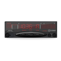
K3
ISOLATED INTERFACE CONVERTER
RS232
RS232/RS485
WWW.KKSYSTEMS.COM
RS232
↔ RS422/RS485
SYSTEMS
K
L Cable-termination : for long cables it may help to fit a 120 Ω resistor, in series with a 1
nF capacitor, between the TX+ and TX- connections inside the 9-way D-type plug.
See datasheets on the supplied CD for the K3 receiver, and MAX483 line driver.
21