●Troubleshooting
105
7
Troubleshooting
Troubleshooting
5
Troubleshooting
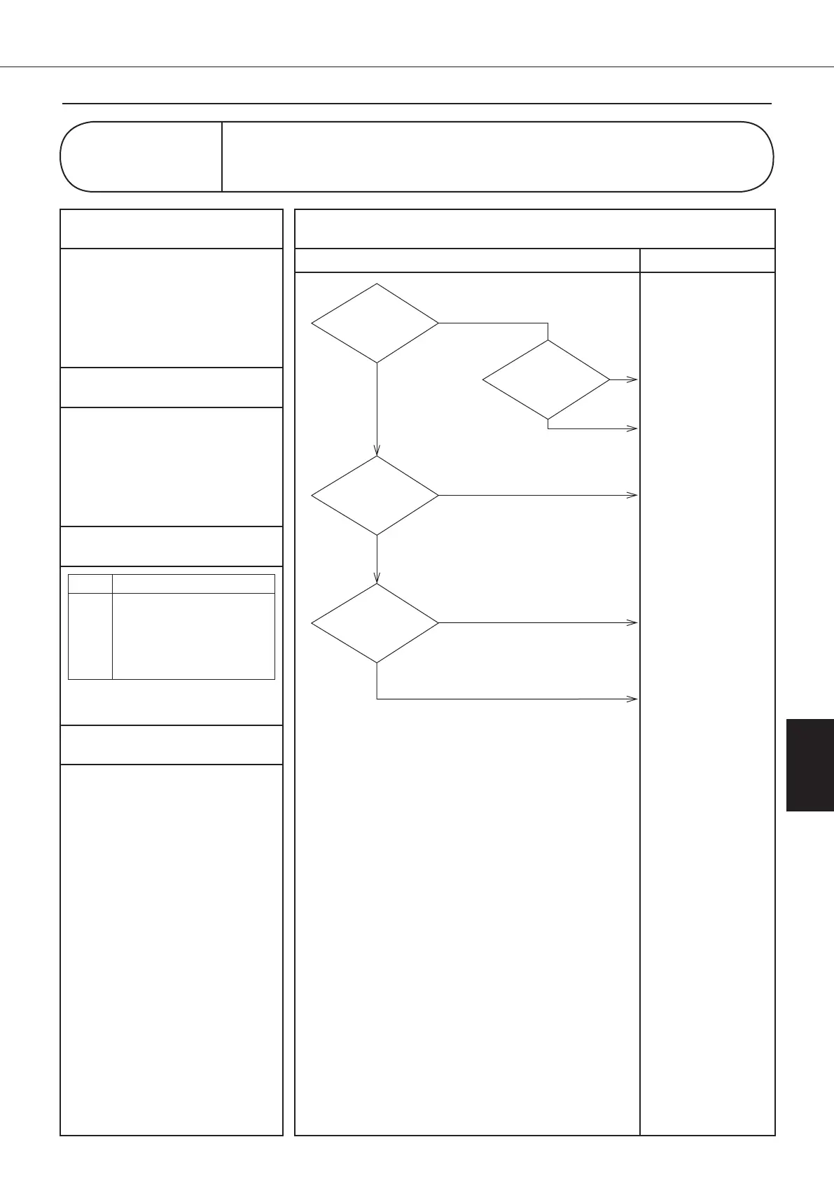
Diagnosis Countermeasures
1
Applicable Models
AKZ**A (All series)
2
Methods of Malfunction Detection
Check communication
conditions between the
inverter microcomputer and
the temperature control
microcomputer
3
Malfunction Decision Conditions
Class Conditions
10, 11
When the transmission
is not performed
normally for a period of
given time or more.
(Retry: 20 times)
4
Supposed Causes
1Faulty control board (A1P)
1Faulty inverter board (A2P)
1External noises or else
Control panel display
LC
Malfunction of Transmission between Inverter CPU and
Temperature Control CPU
Take measures against
the noises.
Check to be sure noises
that are not normally
produced and then take
measures against these
noises.
YES
The power
supply line contains
noises.
NO
Replace the inverter
board (A2P).
(See page 126/141)
NO
NO
The LED300
blinking. (Inverter board)
"Check 4"
(See page 117)
YES
Connect properly.
Replace the control
board (A1P).
(See page 122/137)
YES
NO
The LED140
blinking. (Control board)
"Check 4"
(See page 117)
Is there
any missing between
connectors of the control board and the
inverter board
(S140-CN110)?
YES
00_PB00540A_M10.indb 105 2023/08/09 12:59:07