155
●Miscellaneous Reference Data
10
Miscellaneous Reference Data
Miscellaneous
Reference Data
Notes on Installation
3
For an installation place, observe the following.
Do not place an object that may block air flow within 500 mm from the air intake/exhaust port.
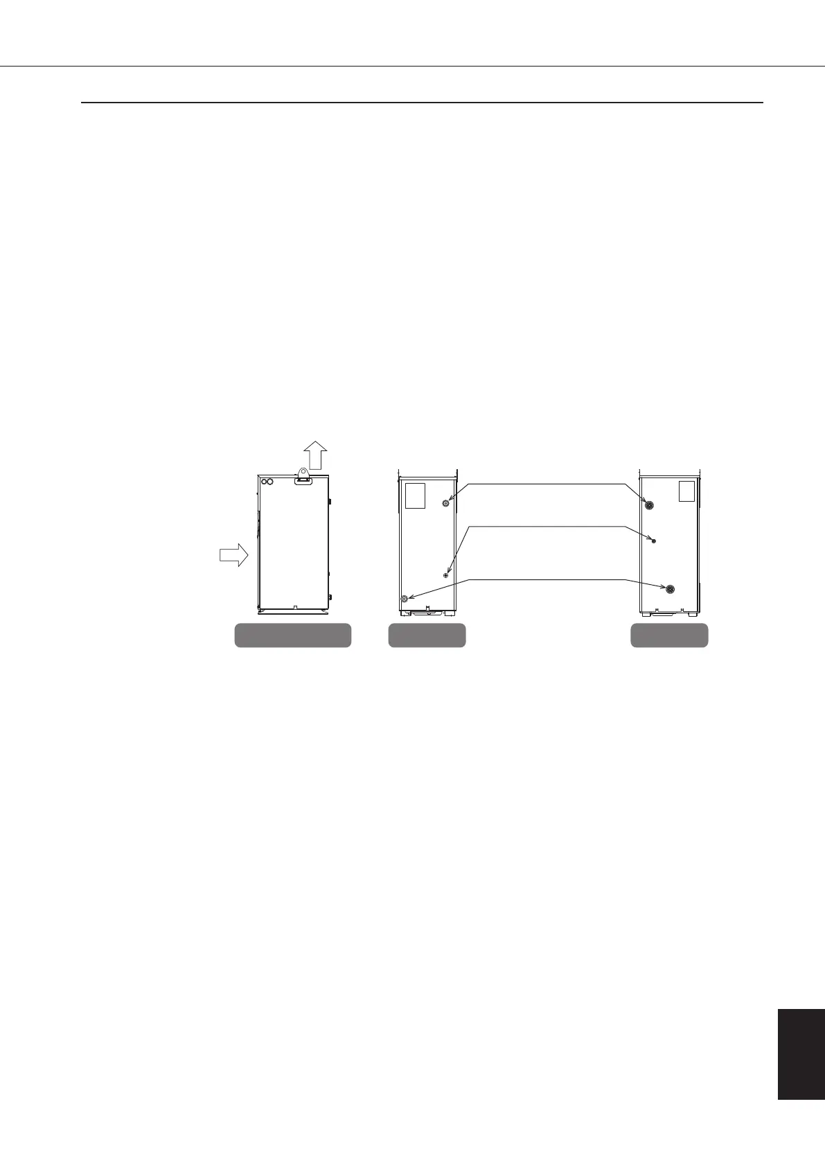
Oil piping: Locations of the oil inlet, oil outlet and oil drain are shown below.
Oil may remain inside the OILCON, so prepare something to catch the oil, such as an oil tray.
• If the evaporator (cooler) in the Oil Cooling Unit is clogged with dust, it causes not only cooling capacity deterioration, but
also a fault of the compressor or oil pump.
• During adjustment at trial run, the strainer gathers much dust from the oil piping system. Clean or replace the strainer
before starting actual operation. Check the strainer periodically.
• The oil pollution level must not exceed NAS class 10.
Attach a strainer (mesh size: 100 to 150) with a small pressure loss to the oil piping system.
•
To receive oil from the main machine oil piping system, provide an oil tank that can accept an increase/decrease in oil quantity.
•
Consider the tank structure so that inside of the tank can be easily cleaned. (For example, the tank has a cleaning hole or the
tank top plate is detachable.)
•
Before the start of operation, make sure that the tank is filled with oil to an appropriate level.
1.
Horizontal and rugged floor face (vertical interval 5 mm or less)
When you install the product, fix it with a bolt (M10×20
hexagonal bolt is recommended).
2.
A place where the unit is not exposed to direct sunlight or heat
3.
A place with proper ventilation and little humidity
4.
A place where exhaust air does not circulate (exhaust air will
not be taken into the unit)
5.
A place that allows easy access to piping and wiring
6.
A place with little contaminant, waste, dust particles or oil
mist
(Ensure that no foreign matter enters the electric component
box.)
7.
A place free from explosive atmosphere (evolution, inflow,
retention or leak of inflammable gas)
8.
Do not install the unit outdoors.
9.
Install the unit within 1 m of the tank level. (Otherwise, it will
affect the sucking capability of the pump.)
10.
Keep any electrical noise generating devices away from the
unit. If it is difficult to do so, implement appropriate measures
on the noise generating devices.
11.
Leave safe, sufficient space around the unit to ensure proper,
trouble-free operations of the control panel.
12.
Do not install at an altitude of 2,000m or more.
1. Make sure that the pressure loss at the oil inlet/outlet is within the following range:
• Suction pressure (at oil inlet) .......................... –30.7 to 0 kPa
• Discharge pressure (at oil outlet) .................... 0.5 MPa or less
However, if the atmospheric pressure drops, use thorough caution about suction pressure.
In case atmospheric pressure drops, be careful of the decrease of inlet suction pressure.
(Reference) Reduction of the pressure at altitude:–1kPa/100m
2. Use piping that can withstand a pressure of more than 1MPa and with oil resistance characteristics, and avoid using a
valve in the middle of the piping as much as possible.
If a valve is used, it causes a large pressure loss even when it is fully opened.
3. If the oil viscosity is high, or if there is a large pressure loss in external piping (other than the piping for the Oil Cooling
Unit), use a pipe with a larger diameter to reduce the pressure loss.
If the operating condition exceeds the specified range, it causes noise or fault of the unit. Use thorough caution about
the operating condition. Keep the oil viscosity at 1.4 to 200 mm
2
/s.
4. To prevent air entry or oil leak, wrap the pipe joints with sealing tape, etc.
5. Make sure that the oil piping of the main machine is not blocked (fully closed).
Exhaust air
Intake air
AKZ56A,90AAKZ14A,32A,43A
Right side view Rear view Rear view
OIL OUTLET
OIL INLET
OIL DRAIN
(No connection)
3-1. Installing Location and Oil Piping
3-3. Oil Tank
3-2. Suction Strainer (Line Filter)
00_PB00540A_M10.indb 155 2023/08/09 12:59:27