158
10
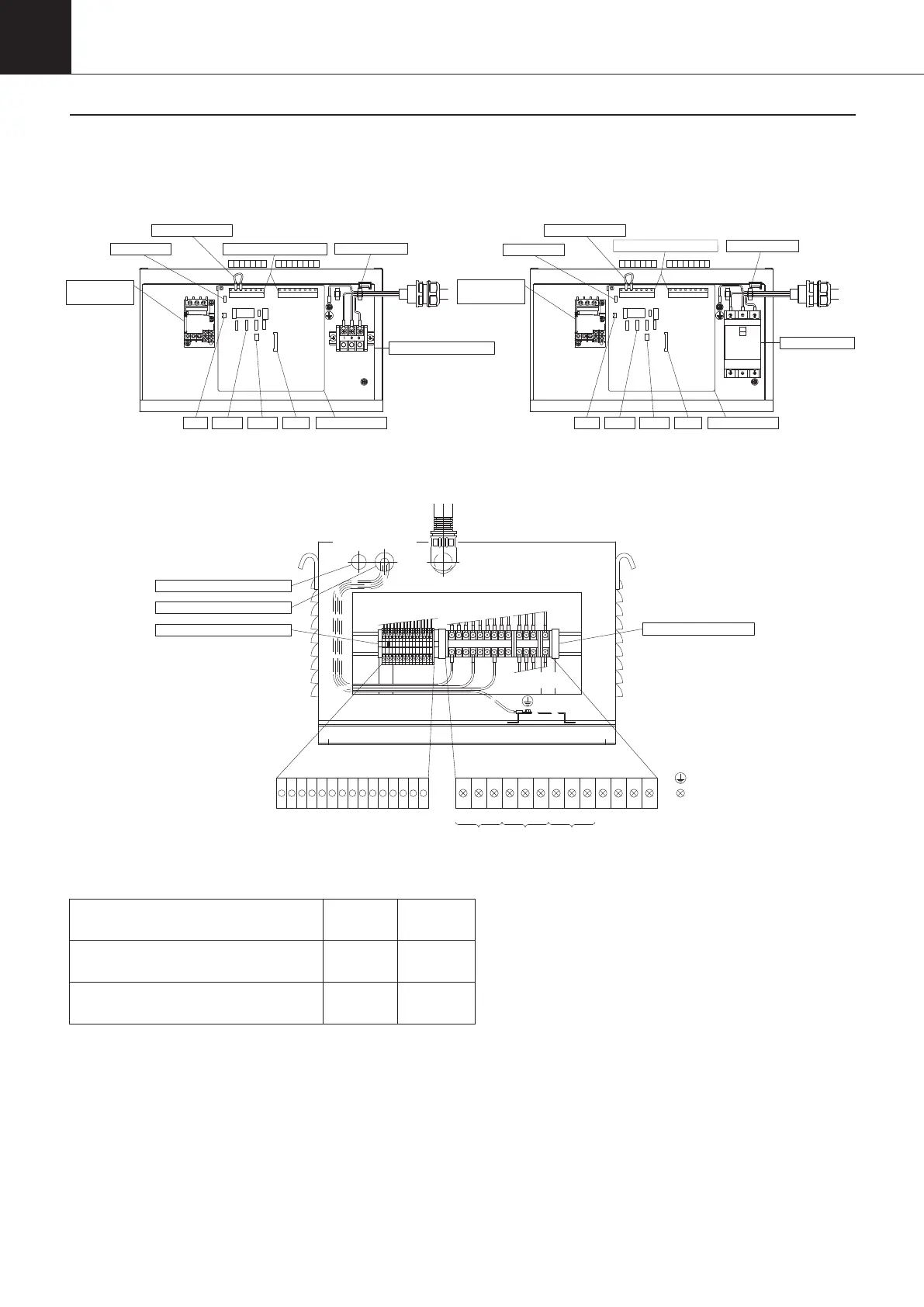
Miscellaneous Reference Data
Built-in breaker model (B)Terminal block for standard model
(Including -C, -H and -T)
• Protect switch (erroneous operation prevention)
The factory setting of this switch is OFF but some nonstandard units are set to ON.
Pay attention when you attempt to change any of the operation setting, parameter setting or timer setting.
• Connector CN2 (Option OP2 terminal)
Alarm will be generated on malfunction by connecting an external protecting device and setting the parameter
(n003)
• Connector CN11
Replace this connector with the outlet oil thermistor when you attempt returned oil temperature control.
• Connector CN12
Connect the lead provided in the unit to the optional communication board.
• Connector S151
Connect the lead provided in the unit to the optional communication board.
9 10 11 13 30 3112
60 61 62 64 65 6663 67
9 10 11 13 30 3112 60 61 62 64 6663 6765
For different-voltage model (-048)*
(* Wiring connection example when the voltage is 440V)
Terminal block for standard model
(Including -C, -H, and -T)
Breaker terminals (-B)
Transformer terminals (-048)
M4, M5
M5
M4
0.98–1.47
2–3
1.2–2.0
Terminal screw size and tightening torque
(N·m)
9 10 11 12 13 30 31 60 61 62 63 64 65 66 67
440V 460 480 440 460 480 440 460 480-048:
Select a terminal according to the main power supply voltage.
U WV
Earth
Our internal wiring
Our internal wiring
Transformer box
Power cable insertion hole
Signal cable insertion hole
Power terminal block
Customer’s wiring
Signal terminal block
CN12CN2 CN11
Signal terminal block
S151
Anchor mount
Short-circuit bar
Over-current
Relay
Control board
Protect SW
Customer’s wiring
Signal terminal block
Protect SW
Short-circuit bar
Customer’s
wiring
Circuit breaker
CN12CN2 CN11
S151
Over-current
Relay
Control board
Power terminal block
Anchor mount
4-4. Switch Box Outline
00_PB00540A_M10.indb 158 2023/08/09 12:59:28