86
7
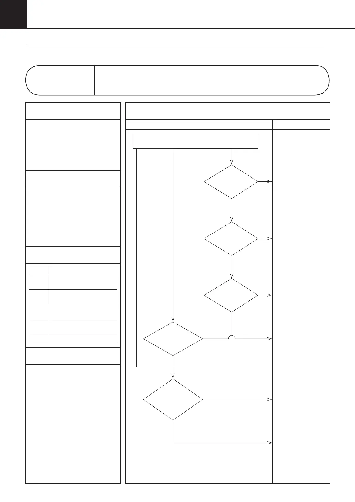
Troubleshooting
5
Troubleshooting
Diagnosis Countermeasures
NO
Does
the power supply
voltage fall within the
range of rating
±10%?
NO
LED lamp is
blinking (Inverter board)
"Check 4"
(See page 117)
YES
Connect the connectors properly.
・
Are the connectors connected as shown
in the wiring diagram?
・
Are the connectors securely pressed in?
(Check at five locations.)
・
Is there any broken wire in the
connectors?
Are foreign
matters caught
in the propeller
fan?
NO
NO
Are the
connectors (CN103,
CN650, X500, X530,CN15) properly
connected?
YES
A6.70
A6.71
A6.72
A6.73
A6.74
A6.76
YES
YES
YES
Is the fan
rotating?
NO
Correct the power
supply voltage.
Replace the inverter
board (A2P).
Replace the fan motor
(M3F).
Check the alarm code in service monitor mode.
Replace the control
board (A1P).
(See page 122/137)
Control panel display
A6
Malfunction of DC Fan Motor
1
Applicable Models
AKZ14A–43A
2
Methods of Malfunction Detection
1. DC voltage in the main
circuit at the inverter board
(A2P) input section
2. Detected fan revolutions
3. Faulty signal between the
fan motor (M3F) and the
inverter board (A2P)
3
Malfunction Decision Conditions
Class Conditions
70
When the main circuit for fan has
abnormal instantaneous overcurrent.
71
When the hall sensor of
the fan motor is abnormal.
72
When an error signal is
detected from the power device.
73, 74
When the main circuit for fan
has an abnormal voltage.
76
When the fan does not rotate.
4
Supposed Causes
1Faulty connector connection
1Disconnected wiring
1Faulty control board (A1P)
1Faulty inverter board (A2P)
1Faulty fan motor (M3F)
1 Surge in power supply
1 Noise from power supply
3-3. Troubleshooting Flowchart
00_PB00540A_M10.indb 86 2023/08/09 12:59:05